Dell PowerEdge 1950 Hardware Owner's Manual (PDF) - Page 63
Configuring the Boot Device, System Memory - ii
 |
View all Dell PowerEdge 1950 manuals
Add to My Manuals
Save this manual to your list of manuals |
Page 63 highlights
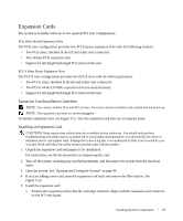
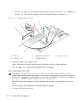
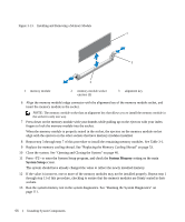
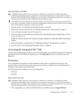
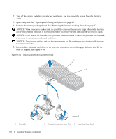
4 Remove the expansion card: a Open the expansion-card latch. See Figure 3-12. b Grasp the expansion card by its edges, and carefully remove it from the expansion-card connector. 5 If you are removing the card permanently, install a metal filler bracket over the empty expansion slot opening and close the expansion-card latch. NOTE: You must install a filler bracket over an empty expansion slot to maintain Federal Communications Commission (FCC) certification of the system. The brackets also keep dust and dirt out of the system and aid in proper cooling and airflow inside the system. 6 Close the system. See "Opening and Closing the System" on page 46. Configuring the Boot Device If you plan to boot the system from a hard drive, the drive must be attached to the primary (or boot) controller. The device that the system boots from is determined by the boot order specified in the System Setup program. The System Setup program provides options that the system uses to scan for installed boot devices. See "Using the System Setup Program" on page 31 for information about the System Setup program. Configuring the Boot Drive The drive or device from which the system boots is determined by the boot order specified in the System Setup program. See "Using the System Setup Program" on page 31 for information about the System Setup program. System Memory You can upgrade your system memory to a maximum of 32 GB by installing 533-MHz or 667-MHz fully buffered (FB) DDR II memory modules (DIMMs) in sets of 256-MB, 512-MB, 1-GB, 2-GB, or 4-GB modules. The eight memory sockets are located on the system board under the memory cooling shroud.You can purchase memory upgrade kits from Dell. NOTICE: If you remove your original memory modules from the system during a memory upgrade, keep them separate from any new memory modules that you may have, even if you purchased the new memory modules from Dell. Use only 533-MHz or 667-MHz DDR II fully buffered DIMMS (FBDs). The memory module sockets are divided into two equal branches (0 and 1). Each branch consists of two channels: • Channel 0 and channel 1 are in branch 0. • Channel 2 and channel 3 are in branch 1. Installing System Components 63
-
 1
1 -
2
-
3
-
4
-
5
-
6
-
7
-
8
-
9
-
10
-
11
-
12
-
13
-
14
-
15
-
16
-
17
-
18
-
19
-
20
-
21
-
22
-
23
-
24
-
25
-
26
-
27
-
28
-
29
-
30
-
31
-
32
-
33
-
34
-
35
-
36
-
37
-
38
-
39
-
40
-
41
-
42
-
43
-
44
-
45
-
46
-
47
-
48
-
49
-
50
-
51
-
52
-
53
-
54
-
55
-
56
-
57
-
 58
58 -
 59
59 -
 60
60 -
 61
61 -
 62
62 -
 63
63 -
 64
64 -
 65
65 -
 66
66 -
 67
67 -
 68
68 -
69
-
70
-
71
-
72
-
73
-
74
-
75
-
76
-
77
-
78
-
79
-
80
-
81
-
82
-
83
-
84
-
85
-
86
-
87
-
88
-
89
-
90
-
91
-
92
-
93
-
94
-
95
-
96
-
97
-
98
-
99
-
100
-
101
-
102
-
103
-
104
-
105
-
106
-
107
-
108
-
109
-
110
-
111
-
112
-
113
-
114
-
115
-
116
-
117
-
118
-
119
-
120
-
121
-
122
-
123
-
124
-
125
-
126
-
127
-
128
-
129
-
130
-
131
-
132
-
133
-
134
-
135
-
136
-
137
-
138
-
139
-
140
-
141
-
142
-
143
-
144
-
145
-
146
-
147
-
148
-
149
-
150
-
151
-
152
-
153
-
154
-
155
-
156
-
157
-
158
-
159
-
160
 |
 |