Dell PowerEdge 1950 Hardware Owner's Manual (PDF) - Page 45
Removing and Replacing the Front Bezel - memory slots
 |
View all Dell PowerEdge 1950 manuals
Add to My Manuals
Save this manual to your list of manuals |
Page 45 highlights
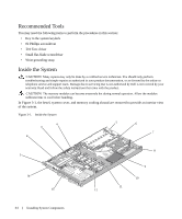
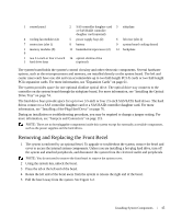
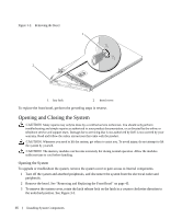
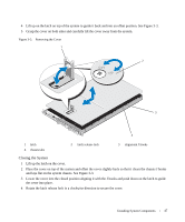
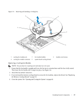
1 control panel 2 SAS controller daughter card 3 sideplane or SAS RAID controller daughter card (optional) 4 cooling fan modules (4) 5 power supply bays (2) 6 left riser (slot 2) 7 center riser (slot 1) 8 battery 9 system board cooling shroud 1 memory modules (8) 0 11 heatsink/microprocessor (2) 12 backplane 1 two 3.5-inch or four 2.5-inch 14 optical slimline drive 3 hard drive bays (optional) The system board holds the system's control circuitry and other electronic components. Several hardware options, such as the microprocessors and memory, are installed directly on the system board. The left and center risers each have one slot and can accommodate up to two half-length PCI-X cards or two half-length PCIe expansion cards. For more information, see "Expansion Cards" on page 61. The system provides space for one optional slimline optical drive. The optical drive tray connects to the controller on the system board through the sideplane board. For more information, see "Installing the Optical Drive Tray" on page 74. The hard-drive bays provide space for up to two 3.5-inch or four 2.5-inch SAS/SATA hard drives. The hard drives connect to a SAS controller daughter card or a SAS RAID controller daughter card. For more information, see "Installing a Hot-Plug Hard Drive" on page 76. During an installation or troubleshooting procedure, you may be required to change a jumper setting. For more information, see "Jumpers and Connectors" on page 115. NOTE: There are no hot-pluggable components inside this system except for externally accessible components, such as the power supplies and the hard drives. Removing and Replacing the Front Bezel 1 The system is enclosed by an optional bezel. To upgrade or troubleshoot the system, remove the bezel and cover to access the internal system components. Unless you are installing a hot-plug hard drive, turn off the system and attached peripherals, and disconnect the system from the electrical outlet and peripherals. NOTE: You do not need to remove the front bezel to remove the system cover. 2 Using the system key, unlock the bezel. 3 Press the tab at the left end of the bezel. 4 Rotate the left end of the bezel away from the system to release the right end of the bezel. 5 Pull the bezel away from the system. See Figure 3-2. Installing System Components 45
-
 1
1 -
2
-
3
-
4
-
5
-
6
-
7
-
8
-
9
-
10
-
11
-
12
-
13
-
14
-
15
-
16
-
17
-
18
-
19
-
20
-
21
-
22
-
23
-
24
-
25
-
26
-
27
-
28
-
29
-
30
-
31
-
32
-
33
-
34
-
35
-
36
-
37
-
38
-
39
-
 40
40 -
 41
41 -
 42
42 -
 43
43 -
 44
44 -
 45
45 -
 46
46 -
 47
47 -
 48
48 -
 49
49 -
 50
50 -
51
-
52
-
53
-
54
-
55
-
56
-
57
-
58
-
59
-
60
-
61
-
62
-
63
-
64
-
65
-
66
-
67
-
68
-
69
-
70
-
71
-
72
-
73
-
74
-
75
-
76
-
77
-
78
-
79
-
80
-
81
-
82
-
83
-
84
-
85
-
86
-
87
-
88
-
89
-
90
-
91
-
92
-
93
-
94
-
95
-
96
-
97
-
98
-
99
-
100
-
101
-
102
-
103
-
104
-
105
-
106
-
107
-
108
-
109
-
110
-
111
-
112
-
113
-
114
-
115
-
116
-
117
-
118
-
119
-
120
-
121
-
122
-
123
-
124
-
125
-
126
-
127
-
128
-
129
-
130
-
131
-
132
-
133
-
134
-
135
-
136
-
137
-
138
-
139
-
140
-
141
-
142
-
143
-
144
-
145
-
146
-
147
-
148
-
149
-
150
-
151
-
152
-
153
-
154
-
155
-
156
-
157
-
158
-
159
-
160
 |
 |
