Dell PowerEdge 1950 Hardware Owner's Manual (PDF) - Page 89
Installing the Control Panel, Affix the control panel label to the display module.
 |
View all Dell PowerEdge 1950 manuals
Add to My Manuals
Save this manual to your list of manuals |
Page 89 highlights
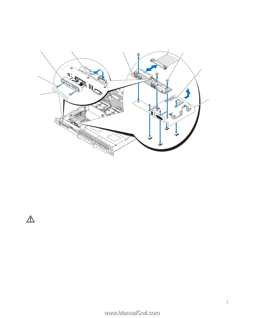
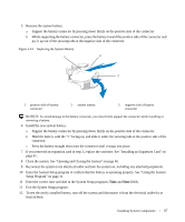
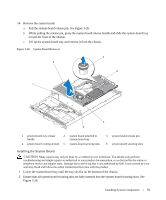
Figure 3-25. Control Panel Removal and Installation 1 2 3 9 8 4 5 6 7 1 display module 4 control panel cable 7 control panel carrier 2 display module LCD cable 5 control-panel circuit board securing screws (3) 8 display module label 3 control panel circuit board 6 control panel carrier release tab 9 display module securing screws (2) Installing the Control Panel CAUTION: Many repairs may only be done by a certified service technician. You should only perform troubleshooting and simple repairs as authorized in your product documentation, or as directed by the online or telephone service and support team. Damage due to servicing that is not authorized by Dell is not covered by your warranty. Read and follow the safety instructions that came with the product. 1 Insert the display module into the chassis cutout and secure it with the two screws. 2 Affix the control panel label to the display module. 3 Install the control panel board on the carrier, and secure it with the three Phillips screws. See Figure 3-25. 4 Install the carrier in the system chassis. 5 Connect the display module ribbon cable to the control panel board. 6 Connect the control panel ribbon cable to the control panel board. Installing System Components 89
-
 1
1 -
2
-
3
-
4
-
5
-
6
-
7
-
8
-
9
-
10
-
11
-
12
-
13
-
14
-
15
-
16
-
17
-
18
-
19
-
20
-
21
-
22
-
23
-
24
-
25
-
26
-
27
-
28
-
29
-
30
-
31
-
32
-
33
-
34
-
35
-
36
-
37
-
38
-
39
-
40
-
41
-
42
-
43
-
44
-
45
-
46
-
47
-
48
-
49
-
50
-
51
-
52
-
53
-
54
-
55
-
56
-
57
-
58
-
59
-
60
-
61
-
62
-
63
-
64
-
65
-
66
-
67
-
68
-
69
-
70
-
71
-
72
-
73
-
74
-
75
-
76
-
77
-
78
-
79
-
80
-
81
-
82
-
83
-
 84
84 -
 85
85 -
 86
86 -
 87
87 -
 88
88 -
 89
89 -
 90
90 -
 91
91 -
 92
92 -
 93
93 -
 94
94 -
95
-
96
-
97
-
98
-
99
-
100
-
101
-
102
-
103
-
104
-
105
-
106
-
107
-
108
-
109
-
110
-
111
-
112
-
113
-
114
-
115
-
116
-
117
-
118
-
119
-
120
-
121
-
122
-
123
-
124
-
125
-
126
-
127
-
128
-
129
-
130
-
131
-
132
-
133
-
134
-
135
-
136
-
137
-
138
-
139
-
140
-
141
-
142
-
143
-
144
-
145
-
146
-
147
-
148
-
149
-
150
-
151
-
152
-
153
-
154
-
155
-
156
-
157
-
158
-
159
-
160
 |
 |