Dell PowerEdge 1950 Hardware Owner's Manual (PDF) - Page 64
General Memory Module Installation Guidelines, Non-Optimal Memory Configurations
 |
View all Dell PowerEdge 1950 manuals
Add to My Manuals
Save this manual to your list of manuals |
Page 64 highlights
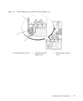
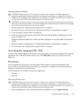
Each channel consists of two memory module sockets: • Channel 0 contains DIMM_1, DIMM_5. • Channel 1 contains DIMM _2, DIMM_6. • Channel 2 contains DIMM_3, DIMM_7. • Channel 3 contains DIMM _4, DIMM _8. The first DIMM socket of each channel has white release tabs. General Memory Module Installation Guidelines To ensure optimal performance of your system, observe the following guidelines when configuring your system memory. • Use only qualified FBDs. FBDs can be either single-ranked or dual-ranked. FBDs marked with a 1R are single-ranked and modules marked with a 2R are dual-ranked. • A minimum of two identical FBDs must be installed. • DIMM sockets must be populated by lowest number first. • Memory modules must be installed in pairs of matched memory size, speed, and technology, and the total number of memory modules in the configuration must total two, four, or eight. For best system performance, all four, or eight memory modules should be identical in size, speed, and technology. • Memory sparing and memory mirroring require eight memory, and all memory modules must be of identical memory size, speed, and technology. • Memory sparing and memory mirroring cannot be implemented at the same time. Non-Optimal Memory Configurations System performance can be affected if your memory configuration does not conform to the preceding installation guidelines. Your system may issue an error message during startup stating that your memory configuration is non-optimal. Memory Sparing Support The system supports memory sparing if eight identical memory modules are installed in the system. The memory sparing feature must be enabled in the System Setup program and can be used only if memory mirroring is not enabled.(See "Using the System Setup Program" on page 31.) Memory sparing allocates four ranks of DIMM memory to the spare bank. These four ranks consist of the first rank of memory in DIMM sockets 1 through 4. For single-rank DIMMs, the entire capacity of the four DIMMs is allocated to sparing whereas for dual-rank DIMMs, only half of the four-DIMM capacity is allocated to sparing. Table 3-1 shows how memory sparing splits the available and spared memory in each of the single- and dual-ranked memory module combinations. 64 Installing System Components
-
 1
1 -
2
-
3
-
4
-
5
-
6
-
7
-
8
-
9
-
10
-
11
-
12
-
13
-
14
-
15
-
16
-
17
-
18
-
19
-
20
-
21
-
22
-
23
-
24
-
25
-
26
-
27
-
28
-
29
-
30
-
31
-
32
-
33
-
34
-
35
-
36
-
37
-
38
-
39
-
40
-
41
-
42
-
43
-
44
-
45
-
46
-
47
-
48
-
49
-
50
-
51
-
52
-
53
-
54
-
55
-
56
-
57
-
58
-
 59
59 -
 60
60 -
 61
61 -
 62
62 -
 63
63 -
 64
64 -
 65
65 -
 66
66 -
 67
67 -
 68
68 -
 69
69 -
70
-
71
-
72
-
73
-
74
-
75
-
76
-
77
-
78
-
79
-
80
-
81
-
82
-
83
-
84
-
85
-
86
-
87
-
88
-
89
-
90
-
91
-
92
-
93
-
94
-
95
-
96
-
97
-
98
-
99
-
100
-
101
-
102
-
103
-
104
-
105
-
106
-
107
-
108
-
109
-
110
-
111
-
112
-
113
-
114
-
115
-
116
-
117
-
118
-
119
-
120
-
121
-
122
-
123
-
124
-
125
-
126
-
127
-
128
-
129
-
130
-
131
-
132
-
133
-
134
-
135
-
136
-
137
-
138
-
139
-
140
-
141
-
142
-
143
-
144
-
145
-
146
-
147
-
148
-
149
-
150
-
151
-
152
-
153
-
154
-
155
-
156
-
157
-
158
-
159
-
160
 |
 |