Dell PowerEdge 1950 Hardware Owner's Manual (PDF) - Page 90
System Board, Removing the System Board - fan
 |
View all Dell PowerEdge 1950 manuals
Add to My Manuals
Save this manual to your list of manuals |
Page 90 highlights
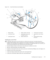
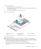
7 Replace the SAS controller daughter card. See "Installing a SAS Controller Daughter Card or SAS RAID Controller Daughter Card" on page 56. 8 Close the system. See "Opening and Closing the System" on page 46. 9 Reconnect the system to the power source and turn on the system and attached peripherals. 10 If applicable, install the bezel. See "Removing and Replacing the Front Bezel" on page 45. System Board Removing the System Board CAUTION: Many repairs may only be done by a certified service technician. You should only perform troubleshooting and simple repairs as authorized in your product documentation, or as directed by the online or telephone service and support team. Damage due to servicing that is not authorized by Dell is not covered by your warranty. Read and follow the safety instructions that came with the product. 1 If applicable, remove the bezel. See "Removing and Replacing the Front Bezel" on page 45. 2 Turn off the system and attached peripherals, and disconnect the system from the electrical outlet. 3 Open the system. See "Opening and Closing the System" on page 46. 4 Disconnect any cables from the system board back panel. 5 Remove the memory cooling shroud. See "Removing the Memory Cooling Shroud" on page 52. 6 Remove both power supplies. See "Removing a Power Supply" on page 54. 7 Remove the sideplane from the system board. See "Removing the Sideplane Board" on page 85. 8 Remove both the center and left risers from the system board. See "Removing an Expansion-Card Riser" on page 82. 9 Remove the four fan modules. See "Removing a Cooling Fan Module" on page 48. 10 If applicable, remove the RAC card. See "RAC Card" on page 71. 11 Remove the memory modules. See "Removing Memory Modules" on page 67. CAUTION: The memory modules are hot to the touch for some time after the system has been powered down. Allow time for the memory modules to cool before handling them. Handle the memory modules by the card edges and avoid touching the components on the memory module. NOTE: While removing the memory modules, record the memory module socket locations to ensure proper installation. NOTE: Your system also comes with a pre installed system board cooling shroud. Do not remove the system board cooling shroud. See Figure 3-5. 12 Remove the heatsink(s) and microprocessor(s). See "Removing the Processor" on page 67. 13 If applicable, remove the TOE key. See "Activating the Integrated NIC TOE" on page 67. 90 Installing System Components
-
 1
1 -
2
-
3
-
4
-
5
-
6
-
7
-
8
-
9
-
10
-
11
-
12
-
13
-
14
-
15
-
16
-
17
-
18
-
19
-
20
-
21
-
22
-
23
-
24
-
25
-
26
-
27
-
28
-
29
-
30
-
31
-
32
-
33
-
34
-
35
-
36
-
37
-
38
-
39
-
40
-
41
-
42
-
43
-
44
-
45
-
46
-
47
-
48
-
49
-
50
-
51
-
52
-
53
-
54
-
55
-
56
-
57
-
58
-
59
-
60
-
61
-
62
-
63
-
64
-
65
-
66
-
67
-
68
-
69
-
70
-
71
-
72
-
73
-
74
-
75
-
76
-
77
-
78
-
79
-
80
-
81
-
82
-
83
-
84
-
 85
85 -
 86
86 -
 87
87 -
 88
88 -
 89
89 -
 90
90 -
 91
91 -
 92
92 -
 93
93 -
 94
94 -
 95
95 -
96
-
97
-
98
-
99
-
100
-
101
-
102
-
103
-
104
-
105
-
106
-
107
-
108
-
109
-
110
-
111
-
112
-
113
-
114
-
115
-
116
-
117
-
118
-
119
-
120
-
121
-
122
-
123
-
124
-
125
-
126
-
127
-
128
-
129
-
130
-
131
-
132
-
133
-
134
-
135
-
136
-
137
-
138
-
139
-
140
-
141
-
142
-
143
-
144
-
145
-
146
-
147
-
148
-
149
-
150
-
151
-
152
-
153
-
154
-
155
-
156
-
157
-
158
-
159
-
160
 |
 |