Dell PowerEdge 1950 Hardware Owner's Manual (PDF) - Page 92
Replace the memory cooling shroud. See Replacing the Memory Cooling Shroud - fans
 |
View all Dell PowerEdge 1950 manuals
Add to My Manuals
Save this manual to your list of manuals |
Page 92 highlights
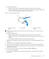
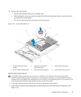
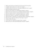
3 Slide the system-board tray toward the back of the chassis until it locks into position. 4 If applicable, replace the RAC card. See "RAC Card" on page 71. 5 If applicable, replace the TOE key. See "Activating the Integrated NIC TOE" on page 67. 6 Replace the heatsink(s) and microprocessor(s). 7 Replace the memory modules. See "Installing Memory Modules" on page 65. 8 Replace both the center and left risers. See "Installing an Expansion-Card Riser" on page 83. 9 Replace any expansion card(s). See "Installing an Expansion Card" on page 61. 10 Replace the sideplane board. See "Installing the Sideplane Board" on page 86. 11 Replace the fan modules. See "Replacing a Cooling Fan Module" on page 49. 12 Replace the memory cooling shroud. See "Replacing the Memory Cooling Shroud" on page 53. 13 Replace the power supplies. See "Replacing a Power Supply" on page 55. 14 Connect any cables to the system. 15 Close the system. See "Opening and Closing the System" on page 46. 16 Replace the bezel. See "Removing and Replacing the Front Bezel" on page 45. 92 Installing System Components
-
 1
1 -
2
-
3
-
4
-
5
-
6
-
7
-
8
-
9
-
10
-
11
-
12
-
13
-
14
-
15
-
16
-
17
-
18
-
19
-
20
-
21
-
22
-
23
-
24
-
25
-
26
-
27
-
28
-
29
-
30
-
31
-
32
-
33
-
34
-
35
-
36
-
37
-
38
-
39
-
40
-
41
-
42
-
43
-
44
-
45
-
46
-
47
-
48
-
49
-
50
-
51
-
52
-
53
-
54
-
55
-
56
-
57
-
58
-
59
-
60
-
61
-
62
-
63
-
64
-
65
-
66
-
67
-
68
-
69
-
70
-
71
-
72
-
73
-
74
-
75
-
76
-
77
-
78
-
79
-
80
-
81
-
82
-
83
-
84
-
85
-
86
-
 87
87 -
 88
88 -
 89
89 -
 90
90 -
 91
91 -
 92
92 -
 93
93 -
 94
94 -
 95
95 -
 96
96 -
 97
97 -
98
-
99
-
100
-
101
-
102
-
103
-
104
-
105
-
106
-
107
-
108
-
109
-
110
-
111
-
112
-
113
-
114
-
115
-
116
-
117
-
118
-
119
-
120
-
121
-
122
-
123
-
124
-
125
-
126
-
127
-
128
-
129
-
130
-
131
-
132
-
133
-
134
-
135
-
136
-
137
-
138
-
139
-
140
-
141
-
142
-
143
-
144
-
145
-
146
-
147
-
148
-
149
-
150
-
151
-
152
-
153
-
154
-
155
-
156
-
157
-
158
-
159
-
160
 |
 |