Dell PowerEdge 1950 Hardware Owner's Manual (PDF) - Page 53
Power Supplies, Replacing the Memory Cooling Shroud
 |
View all Dell PowerEdge 1950 manuals
Add to My Manuals
Save this manual to your list of manuals |
Page 53 highlights
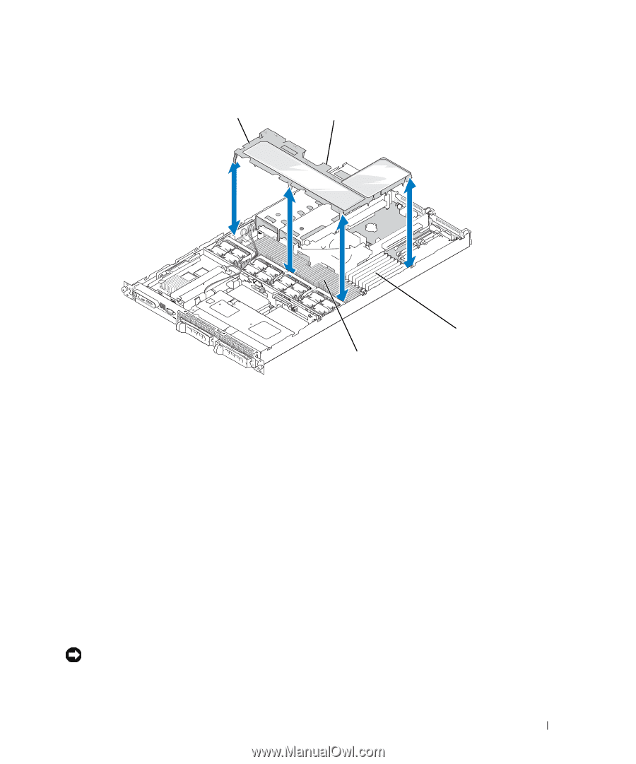
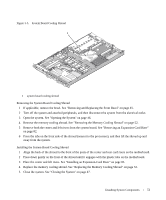
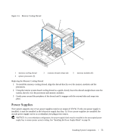
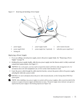
Figure 3-6. Memory Cooling Shroud 1 2 3 4 1 memory cooling shroud 4 system processors (2) 2 memory shroud release tab 3 memory modules (8) Replacing the Memory Cooling Shroud 1 To install the memory cooling shroud, align the shroud directly over the memory modules and the processors. 2 Using the interior system board cooling shroud as a guide, slowly lower the shroud straight down onto the system, directly over the processors and memory modules. 3 Gently press around the periphery of the shroud until it engages with the external tabs and snaps into place. Power Supplies Your system supports one or two power supplies rated at an output of 670 W. If only one power supply is installed, it must be installed in the left power supply bay (bay 1). If two power supplies are installed, the second power supply serves as a redundant, hot-plug power source. NOTICE: In a non-redundant configuration, the power supply blank must be installed in the unoccupied power supply bay to ensure proper system cooling. See "Installing the Power Supply Blank" on page 56. Installing System Components 53
-
 1
1 -
2
-
3
-
4
-
5
-
6
-
7
-
8
-
9
-
10
-
11
-
12
-
13
-
14
-
15
-
16
-
17
-
18
-
19
-
20
-
21
-
22
-
23
-
24
-
25
-
26
-
27
-
28
-
29
-
30
-
31
-
32
-
33
-
34
-
35
-
36
-
37
-
38
-
39
-
40
-
41
-
42
-
43
-
44
-
45
-
46
-
47
-
 48
48 -
 49
49 -
 50
50 -
 51
51 -
 52
52 -
 53
53 -
 54
54 -
 55
55 -
 56
56 -
 57
57 -
 58
58 -
59
-
60
-
61
-
62
-
63
-
64
-
65
-
66
-
67
-
68
-
69
-
70
-
71
-
72
-
73
-
74
-
75
-
76
-
77
-
78
-
79
-
80
-
81
-
82
-
83
-
84
-
85
-
86
-
87
-
88
-
89
-
90
-
91
-
92
-
93
-
94
-
95
-
96
-
97
-
98
-
99
-
100
-
101
-
102
-
103
-
104
-
105
-
106
-
107
-
108
-
109
-
110
-
111
-
112
-
113
-
114
-
115
-
116
-
117
-
118
-
119
-
120
-
121
-
122
-
123
-
124
-
125
-
126
-
127
-
128
-
129
-
130
-
131
-
132
-
133
-
134
-
135
-
136
-
137
-
138
-
139
-
140
-
141
-
142
-
143
-
144
-
145
-
146
-
147
-
148
-
149
-
150
-
151
-
152
-
153
-
154
-
155
-
156
-
157
-
158
-
159
-
160
 |
 |