Dell PowerEdge 1950 Hardware Owner's Manual (PDF) - Page 119
Left Pci-x Riser
 |
View all Dell PowerEdge 1950 manuals
Add to My Manuals
Save this manual to your list of manuals |
Page 119 highlights
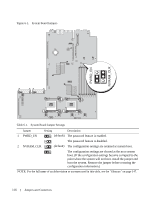
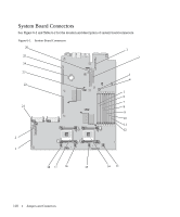
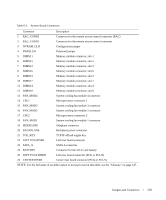
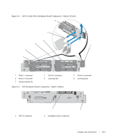
Table 6-2. System Board Connectors Connector Description 1 RAC_CONN2 Connector for the remote access control connector (RAC) 2 RAC_CONN1 Connector for the remote access control connector 3 NVRAM_CLR Configuration jumper 4 PWRD_EN Password jumper 5 DIMM 1 Memory module connector, slot 1 6 DIMM 5 Memory module connector, slot 5 7 DIMM 2 Memory module connector, slot 2 8 DIMM 6 Memory module connector, slot 6 9 DIMM 3 Memory module connector, slot 3 10 DIMM 7 Memory module connector, slot 7 11 DIMM 4 Memory module connector, slot 4 12 DIMM 8 Memory module connector, slot 8 13 FAN_MOD4 System cooling fan module 4 connector 14 CPU1 Microprocessor connector 1 15 FAN_MOD3 System cooling fan module 3 connector 16 FAN_MOD2 System cooling fan module 2 connector 17 CPU2 Microprocessor connector 2 18 FAN_MOD1 System cooling fan module 1 connector 19 SIDEPLANE Sideplane connector 20 BACKPLANE Backplane power connector 21 TOE_KEY TCP/IP offload engine key 22 LEFT PCIe RISER Left riser board connector 23 SATA_A SATA A connector 24 BATTERY Connector for the 3.0-V coin battery 25 LEFT PCI-X RISER Left riser board connector (PCIe or PCI-X) 26 CENTER RISER Center riser board connector (PCIe or PCI-X) NOTE: For the full name of an abbreviation or acronym used in this table, see the "Glossary" on page 147. Jumpers and Connectors 119
-
 1
1 -
2
-
3
-
4
-
5
-
6
-
7
-
8
-
9
-
10
-
11
-
12
-
13
-
14
-
15
-
16
-
17
-
18
-
19
-
20
-
21
-
22
-
23
-
24
-
25
-
26
-
27
-
28
-
29
-
30
-
31
-
32
-
33
-
34
-
35
-
36
-
37
-
38
-
39
-
40
-
41
-
42
-
43
-
44
-
45
-
46
-
47
-
48
-
49
-
50
-
51
-
52
-
53
-
54
-
55
-
56
-
57
-
58
-
59
-
60
-
61
-
62
-
63
-
64
-
65
-
66
-
67
-
68
-
69
-
70
-
71
-
72
-
73
-
74
-
75
-
76
-
77
-
78
-
79
-
80
-
81
-
82
-
83
-
84
-
85
-
86
-
87
-
88
-
89
-
90
-
91
-
92
-
93
-
94
-
95
-
96
-
97
-
98
-
99
-
100
-
101
-
102
-
103
-
104
-
105
-
106
-
107
-
108
-
109
-
110
-
111
-
112
-
113
-
 114
114 -
 115
115 -
 116
116 -
 117
117 -
 118
118 -
 119
119 -
 120
120 -
 121
121 -
 122
122 -
 123
123 -
 124
124 -
125
-
126
-
127
-
128
-
129
-
130
-
131
-
132
-
133
-
134
-
135
-
136
-
137
-
138
-
139
-
140
-
141
-
142
-
143
-
144
-
145
-
146
-
147
-
148
-
149
-
150
-
151
-
152
-
153
-
154
-
155
-
156
-
157
-
158
-
159
-
160
 |
 |