Dell PowerEdge 1950 Hardware Owner's Manual (PDF) - Page 46
Opening and Closing the System, Opening the System
 |
View all Dell PowerEdge 1950 manuals
Add to My Manuals
Save this manual to your list of manuals |
Page 46 highlights
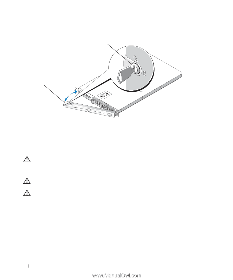
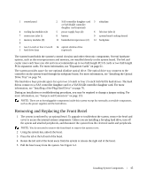
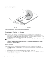
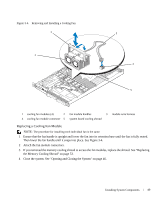
Figure 3-2. Removing the Bezel 1 2 1 key lock 2 bezel cover To replace the front bezel, perform the preceding steps in reverse. Opening and Closing the System CAUTION: Many repairs may only be done by a certified service technician. You should only perform troubleshooting and simple repairs as authorized in your product documentation, or as directed by the online or telephone service and support team. Damage due to servicing that is not authorized by Dell is not covered by your warranty. Read and follow the safety instructions that came with the product. CAUTION: Whenever you need to lift the system, get others to assist you. To avoid injury, do not attempt to lift the system by yourself. CAUTION: The memory modules can become extremely hot during normal operation. Allow the modules sufficient time to cool before handling. Opening the System To upgrade or troubleshoot the system, remove the system cover to gain access to internal components. 1 Turn off the system and attached peripherals, and disconnect the system from the electrical outlet and peripherals. 2 Remove the bezel. See "Removing and Replacing the Front Bezel" on page 45. 3 To remove the system cover, rotate the latch release lock on the latch in a counter clockwise direction to the unlocked position. See Figure 3-3. 46 Installing System Components
-
 1
1 -
2
-
3
-
4
-
5
-
6
-
7
-
8
-
9
-
10
-
11
-
12
-
13
-
14
-
15
-
16
-
17
-
18
-
19
-
20
-
21
-
22
-
23
-
24
-
25
-
26
-
27
-
28
-
29
-
30
-
31
-
32
-
33
-
34
-
35
-
36
-
37
-
38
-
39
-
40
-
 41
41 -
 42
42 -
 43
43 -
 44
44 -
 45
45 -
 46
46 -
 47
47 -
 48
48 -
 49
49 -
 50
50 -
 51
51 -
52
-
53
-
54
-
55
-
56
-
57
-
58
-
59
-
60
-
61
-
62
-
63
-
64
-
65
-
66
-
67
-
68
-
69
-
70
-
71
-
72
-
73
-
74
-
75
-
76
-
77
-
78
-
79
-
80
-
81
-
82
-
83
-
84
-
85
-
86
-
87
-
88
-
89
-
90
-
91
-
92
-
93
-
94
-
95
-
96
-
97
-
98
-
99
-
100
-
101
-
102
-
103
-
104
-
105
-
106
-
107
-
108
-
109
-
110
-
111
-
112
-
113
-
114
-
115
-
116
-
117
-
118
-
119
-
120
-
121
-
122
-
123
-
124
-
125
-
126
-
127
-
128
-
129
-
130
-
131
-
132
-
133
-
134
-
135
-
136
-
137
-
138
-
139
-
140
-
141
-
142
-
143
-
144
-
145
-
146
-
147
-
148
-
149
-
150
-
151
-
152
-
153
-
154
-
155
-
156
-
157
-
158
-
159
-
160
 |
 |