Dell PowerEdge 1950 Hardware Owner's Manual (PDF) - Page 69
Lift the heat sink off of the processor and set the heat sink upside down so as not to contaminate
 |
View all Dell PowerEdge 1950 manuals
Add to My Manuals
Save this manual to your list of manuals |
Page 69 highlights
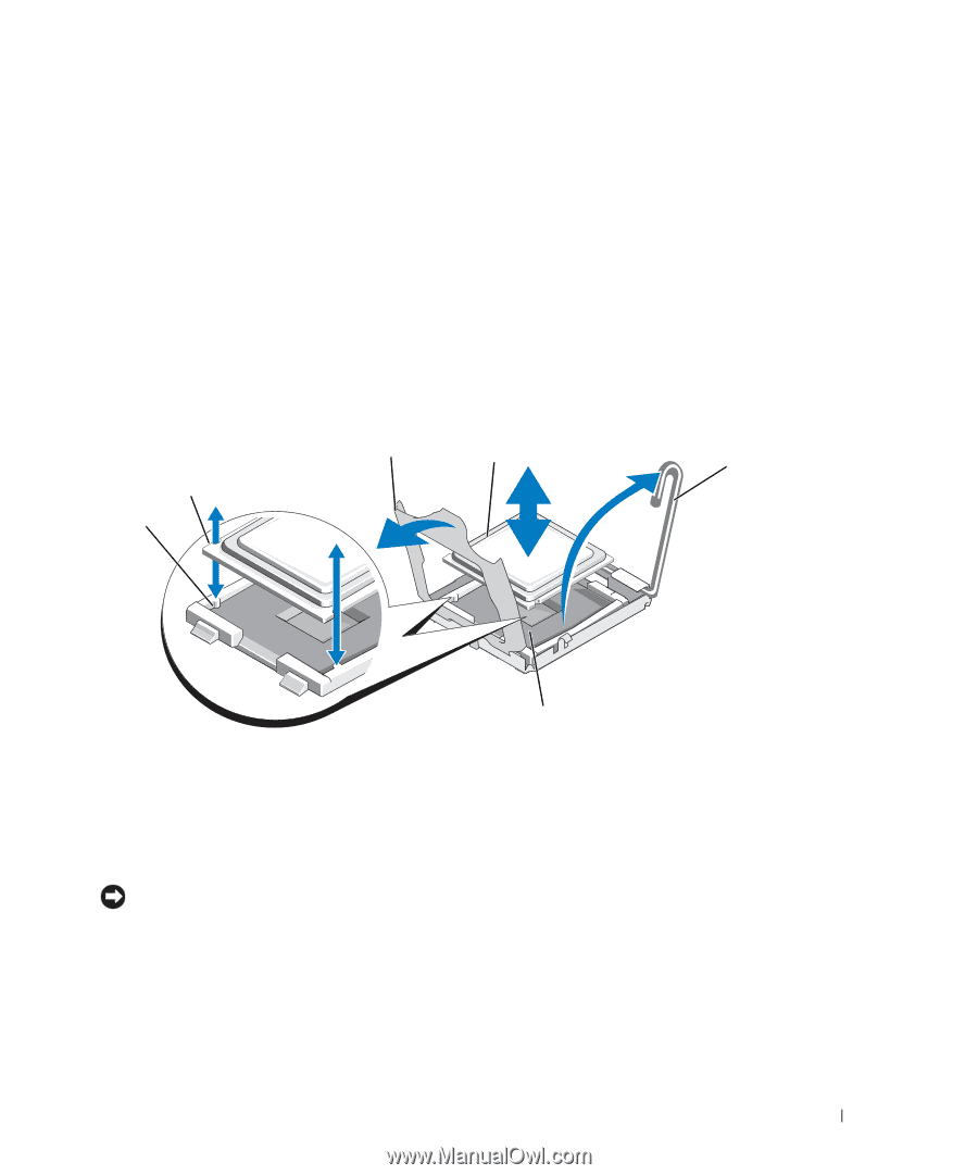
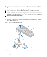
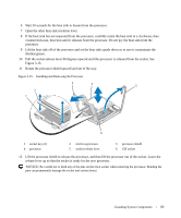
6 Wait 30 seconds for the heat sink to loosen from the processor. 7 Open the other heat sink retention lever. 8 If the heat sink has not separated from the processor, carefully rotate the heat sink in a clockwise, then counterclockwise, direction until it releases from the processor. Do not pry the heat sink from the processor. 9 Lift the heat sink off of the processor and set the heat sink upside down so as not to contaminate the thermal grease. 10 Pull the socket-release lever 90 degrees upward until the processor is released from the socket. See Figure 3-15. 11 Rotate the processor shield upward and out of the way. Figure 3-15. Installing and Removing the Processor 3 4 5 2 1 6 1 socket key (2) 4 processor 2 notch in processor 5 socket-release lever 3 processor shield 6 ZIF socket 12 Lift the processor shield to release the processor, and then lift the processor out of the socket. Leave the release lever up so that the socket is ready for the new processor. NOTICE: Be careful not to bend any of the pins on the LGA socket when removing the processor. Bending the pins can permanently damage the socket and system board. Installing System Components 69
-
 1
1 -
2
-
3
-
4
-
5
-
6
-
7
-
8
-
9
-
10
-
11
-
12
-
13
-
14
-
15
-
16
-
17
-
18
-
19
-
20
-
21
-
22
-
23
-
24
-
25
-
26
-
27
-
28
-
29
-
30
-
31
-
32
-
33
-
34
-
35
-
36
-
37
-
38
-
39
-
40
-
41
-
42
-
43
-
44
-
45
-
46
-
47
-
48
-
49
-
50
-
51
-
52
-
53
-
54
-
55
-
56
-
57
-
58
-
59
-
60
-
61
-
62
-
63
-
 64
64 -
 65
65 -
 66
66 -
 67
67 -
 68
68 -
 69
69 -
 70
70 -
 71
71 -
 72
72 -
 73
73 -
 74
74 -
75
-
76
-
77
-
78
-
79
-
80
-
81
-
82
-
83
-
84
-
85
-
86
-
87
-
88
-
89
-
90
-
91
-
92
-
93
-
94
-
95
-
96
-
97
-
98
-
99
-
100
-
101
-
102
-
103
-
104
-
105
-
106
-
107
-
108
-
109
-
110
-
111
-
112
-
113
-
114
-
115
-
116
-
117
-
118
-
119
-
120
-
121
-
122
-
123
-
124
-
125
-
126
-
127
-
128
-
129
-
130
-
131
-
132
-
133
-
134
-
135
-
136
-
137
-
138
-
139
-
140
-
141
-
142
-
143
-
144
-
145
-
146
-
147
-
148
-
149
-
150
-
151
-
152
-
153
-
154
-
155
-
156
-
157
-
158
-
159
-
160
 |
 |