Dell PowerEdge 1950 Hardware Owner's Manual (PDF) - Page 15
Connecting External Devices, Power Indicator Codes - documentation
 |
View all Dell PowerEdge 1950 manuals
Add to My Manuals
Save this manual to your list of manuals |
Page 15 highlights
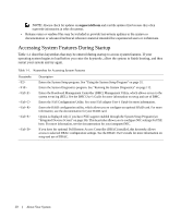
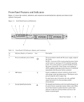
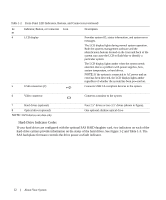
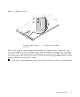
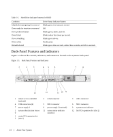
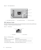
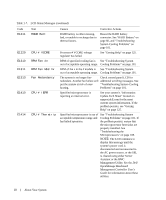
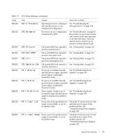
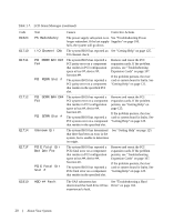
Connecting External Devices When connecting external devices to your system, follow these guidelines: • Most devices must be connected to a specific connector and device drivers must be installed before the device operates properly. (Device drivers are normally included with your operating system software or with the device itself.) See the documentation that accompanied the device for specific installation and configuration instructions. • Always attach external devices while your system is turned off. Next, turn on any external devices before turning on the system (unless the documentation for the device specifies otherwise). For information about individual connectors, see "Jumpers and Connectors" on page 115. For information about enabling, disabling, and configuring I/O ports and connectors, see "Using the System Setup Program" on page 31. Power Indicator Codes The power button on the front panel controls the power input to the system's power supplies. The power indicator can provide information on power status (see Figure 1-1). Table 1-4 lists the power button indicator codes. Table 1-4. Power Button Indicators Indicator On Off Function Indicates that power is supplied to the system and the system is operational. Indicates that no power is supplied to the system. The indicators on the power supplies show whether power is present or whether a power fault has occurred (see Figure 1-4). Table 1-5. Power Supply Indicators Indicator Function Power supply status Green indicates that the power supply is operational. Power supply fault Amber indicates a problem with the power supply. AC line status Green indicates that a valid AC source is connected to the power supply. About Your System 15
-
 1
1 -
2
-
3
-
4
-
5
-
6
-
7
-
8
-
9
-
 10
10 -
 11
11 -
 12
12 -
 13
13 -
 14
14 -
 15
15 -
 16
16 -
 17
17 -
 18
18 -
 19
19 -
 20
20 -
21
-
22
-
23
-
24
-
25
-
26
-
27
-
28
-
29
-
30
-
31
-
32
-
33
-
34
-
35
-
36
-
37
-
38
-
39
-
40
-
41
-
42
-
43
-
44
-
45
-
46
-
47
-
48
-
49
-
50
-
51
-
52
-
53
-
54
-
55
-
56
-
57
-
58
-
59
-
60
-
61
-
62
-
63
-
64
-
65
-
66
-
67
-
68
-
69
-
70
-
71
-
72
-
73
-
74
-
75
-
76
-
77
-
78
-
79
-
80
-
81
-
82
-
83
-
84
-
85
-
86
-
87
-
88
-
89
-
90
-
91
-
92
-
93
-
94
-
95
-
96
-
97
-
98
-
99
-
100
-
101
-
102
-
103
-
104
-
105
-
106
-
107
-
108
-
109
-
110
-
111
-
112
-
113
-
114
-
115
-
116
-
117
-
118
-
119
-
120
-
121
-
122
-
123
-
124
-
125
-
126
-
127
-
128
-
129
-
130
-
131
-
132
-
133
-
134
-
135
-
136
-
137
-
138
-
139
-
140
-
141
-
142
-
143
-
144
-
145
-
146
-
147
-
148
-
149
-
150
-
151
-
152
-
153
-
154
-
155
-
156
-
157
-
158
-
159
-
160
 |
 |