Dell PowerEdge 1950 Hardware Owner's Manual (PDF) - Page 88
Control Panel Assembly, Removing the Control Panel - driver
 |
View all Dell PowerEdge 1950 manuals
Add to My Manuals
Save this manual to your list of manuals |
Page 88 highlights
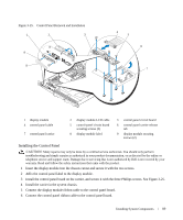
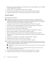
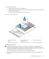
14 After an hour, reconnect the system to its electrical outlet and turn it on. 15 Enter the System Setup program and if the time and date are still incorrect, see "Getting Help" on page 125 for instructions on obtaining technical assistance. Control Panel Assembly Removing the Control Panel CAUTION: Many repairs may only be done by a certified service technician. You should only perform troubleshooting and simple repairs as authorized in your product documentation, or as directed by the online or telephone service and support team. Damage due to servicing that is not authorized by Dell is not covered by your warranty. Read and follow the safety instructions that came with the product. 1 If applicable, remove the bezel. See "Removing and Replacing the Front Bezel" on page 45. 2 Turn off the system and attached peripherals, and disconnect the system from the electrical outlet. 3 Open the system. See "Opening and Closing the System" on page 46. 4 Remove the SAS controller daughter card. See "Removing a SAS Controller Daughter Card" on page 56. 5 Disconnect the control panel cable at the back of the control panel board. See Figure 3-25. NOTICE: Do not pull on the cable to unseat the connector. Doing so can damage the cable. a Squeeze the metal tabs on the ends of the cable connector. b Gently work the connector out of the socket. 6 Disconnect the front panel cable from the control panel board. See Figure 3-25. 7 Lift the release tab at the back of the control panel carrier and slide the carrier towards the back of the system, then lift the carrier out of the system. See Figure 3-25. 8 Remove the three screws that secure the control panel board to the carrier and remove the board. See Figure 3-25. 9 Remove the display module: a Insert the end of a paper clip into the hole on the right side of the display module and gently pry the label off. b Using a T10 Torx driver, remove the two screws that secure the display module to the system chassis. See Figure 3-25. c Remove the display module from the chassis cutout. 88 Installing System Components
-
 1
1 -
2
-
3
-
4
-
5
-
6
-
7
-
8
-
9
-
10
-
11
-
12
-
13
-
14
-
15
-
16
-
17
-
18
-
19
-
20
-
21
-
22
-
23
-
24
-
25
-
26
-
27
-
28
-
29
-
30
-
31
-
32
-
33
-
34
-
35
-
36
-
37
-
38
-
39
-
40
-
41
-
42
-
43
-
44
-
45
-
46
-
47
-
48
-
49
-
50
-
51
-
52
-
53
-
54
-
55
-
56
-
57
-
58
-
59
-
60
-
61
-
62
-
63
-
64
-
65
-
66
-
67
-
68
-
69
-
70
-
71
-
72
-
73
-
74
-
75
-
76
-
77
-
78
-
79
-
80
-
81
-
82
-
 83
83 -
 84
84 -
 85
85 -
 86
86 -
 87
87 -
 88
88 -
 89
89 -
 90
90 -
 91
91 -
 92
92 -
 93
93 -
94
-
95
-
96
-
97
-
98
-
99
-
100
-
101
-
102
-
103
-
104
-
105
-
106
-
107
-
108
-
109
-
110
-
111
-
112
-
113
-
114
-
115
-
116
-
117
-
118
-
119
-
120
-
121
-
122
-
123
-
124
-
125
-
126
-
127
-
128
-
129
-
130
-
131
-
132
-
133
-
134
-
135
-
136
-
137
-
138
-
139
-
140
-
141
-
142
-
143
-
144
-
145
-
146
-
147
-
148
-
149
-
150
-
151
-
152
-
153
-
154
-
155
-
156
-
157
-
158
-
159
-
160
 |
 |