Dell PowerEdge 1950 Hardware Owner's Manual (PDF) - Page 56
Removing the Power Supply Blank, SAS Controller Daughter Card - rails
 |
View all Dell PowerEdge 1950 manuals
Add to My Manuals
Save this manual to your list of manuals |
Page 56 highlights
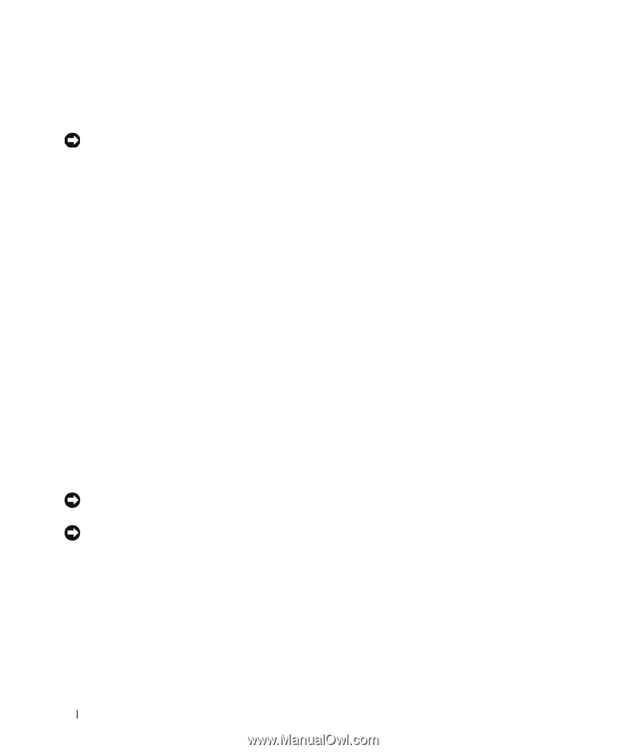
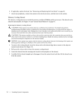
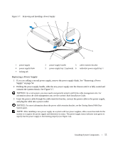
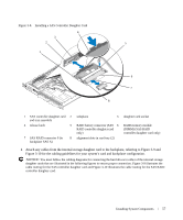
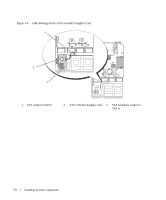
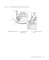
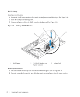
Removing the Power Supply Blank Press the latch on the left side to release and remove the blank, rotating the blank slightly to clear the bay, and remove from the chassis. NOTICE: To ensure proper system cooling, the power supply blank must be installed on the unoccupied power supply bay in a non-redundant configuration. Remove the power supply blank only if you are installing a second power supply. Installing the Power Supply Blank To install the power supply blank, insert the tab on the right edge of the blank into the slot in the power supply bay wall. Rotate the blank into the power supply bay until it is fully seated. SAS Controller Daughter Card Your system includes a dedicated slot on the sideplane for an optional SAS controller daughter card. The SAS controller daughter card provides the SAS storage subsystem for your system's two optional internal hard drives. The optional SAS RAID controller daughter card allows you to set up any internal hard drives in a RAID configuration. Removing a SAS Controller Daughter Card 1 If you are removing a SAS RAID controller daughter card, disconnect the battery cable from the card by releasing the tab on the cable connector on the daughter card. See Figure 3-26. 2 Pull on the release latch on the daughter card (see Figure 3-8) and slide the daughter card tray towards the hard drives. 3 Continue to hold the guide rails outward as you pull the SAS controller daughter card upward from the rails. Installing a SAS Controller Daughter Card or SAS RAID Controller Daughter Card NOTICE: If you are installing a SAS RAID daughter card, be careful not to press on the memory module on the card (see Figure ). to avoid damaging the memory module or its socket. NOTICE: If you are installing a new or replacement SAS RAID daughter card, do not remove the card's plastic cover until you have completed installing the card. 1 Hold the metal daughter card tray by its edges with the release latch and edge connector facing the sideplane board. See Figure 3-8. 2 Align the two slots in the daughter card tray and the corresponding tabs on the chassis, then lower the card tray onto the chassis. 3 Slide the daughter card tray towards the sideplane until the edge connector on the daughter card fits into the socket on the sideplane board and the release latch engages. See Figure 3-8. 56 Installing System Components
-
 1
1 -
2
-
3
-
4
-
5
-
6
-
7
-
8
-
9
-
10
-
11
-
12
-
13
-
14
-
15
-
16
-
17
-
18
-
19
-
20
-
21
-
22
-
23
-
24
-
25
-
26
-
27
-
28
-
29
-
30
-
31
-
32
-
33
-
34
-
35
-
36
-
37
-
38
-
39
-
40
-
41
-
42
-
43
-
44
-
45
-
46
-
47
-
48
-
49
-
50
-
 51
51 -
 52
52 -
 53
53 -
 54
54 -
 55
55 -
 56
56 -
 57
57 -
 58
58 -
 59
59 -
 60
60 -
 61
61 -
62
-
63
-
64
-
65
-
66
-
67
-
68
-
69
-
70
-
71
-
72
-
73
-
74
-
75
-
76
-
77
-
78
-
79
-
80
-
81
-
82
-
83
-
84
-
85
-
86
-
87
-
88
-
89
-
90
-
91
-
92
-
93
-
94
-
95
-
96
-
97
-
98
-
99
-
100
-
101
-
102
-
103
-
104
-
105
-
106
-
107
-
108
-
109
-
110
-
111
-
112
-
113
-
114
-
115
-
116
-
117
-
118
-
119
-
120
-
121
-
122
-
123
-
124
-
125
-
126
-
127
-
128
-
129
-
130
-
131
-
132
-
133
-
134
-
135
-
136
-
137
-
138
-
139
-
140
-
141
-
142
-
143
-
144
-
145
-
146
-
147
-
148
-
149
-
150
-
151
-
152
-
153
-
154
-
155
-
156
-
157
-
158
-
159
-
160
 |
 |