Dell PowerEdge 1950 Hardware Owner's Manual (PDF) - Page 12
Hard-Drive Indicator Codes - hard drive
 |
View all Dell PowerEdge 1950 manuals
Add to My Manuals
Save this manual to your list of manuals |
Page 12 highlights
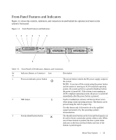
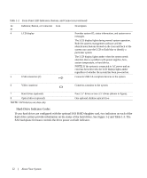
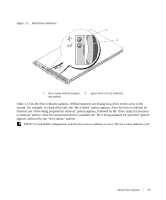
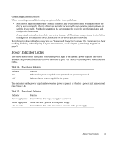
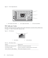
Table 1-2. Front-Panel LED Indicators, Buttons, and Connectors (continued) Ite Indicator, Button, or Connector Icon m 4 LCD display 5 USB connectors (2) Description Provides system ID, status information, and system error messages. The LCD display lights during normal system operation. Both the systems management software and the identification buttons located on the front and back of the system can cause the LCD to flash blue to identify a particular system. The LCD display lights amber when the system needs attention due to a problem with power supplies, fans, system temperature, or hard drives. NOTE: If the system is connected to AC power and an error has been detected, the LCD display lights amber regardless of whether the system has been powered on. Connects USB 2.0-compliant devices to the system. 6 Video connector Connects a monitor to the system. 7 Hard drives (optional) 8 Optical drive (optional) NOTE: DVD devices are data only. Four 2.5" drives or two 3.5" drives (shown in figure). One optional slimline optical drive Hard-Drive Indicator Codes If your hard drives are configured with the optional SAS RAID daughter card, two indicators on each of the hard-drive carriers provide information on the status of the hard drives. See Figure 1-2 and Table 1-3. The SAS backplane firmware controls the drive power-on/fault indicator. 12 About Your System
-
 1
1 -
2
-
3
-
4
-
5
-
6
-
 7
7 -
 8
8 -
 9
9 -
 10
10 -
 11
11 -
 12
12 -
 13
13 -
 14
14 -
 15
15 -
 16
16 -
 17
17 -
18
-
19
-
20
-
21
-
22
-
23
-
24
-
25
-
26
-
27
-
28
-
29
-
30
-
31
-
32
-
33
-
34
-
35
-
36
-
37
-
38
-
39
-
40
-
41
-
42
-
43
-
44
-
45
-
46
-
47
-
48
-
49
-
50
-
51
-
52
-
53
-
54
-
55
-
56
-
57
-
58
-
59
-
60
-
61
-
62
-
63
-
64
-
65
-
66
-
67
-
68
-
69
-
70
-
71
-
72
-
73
-
74
-
75
-
76
-
77
-
78
-
79
-
80
-
81
-
82
-
83
-
84
-
85
-
86
-
87
-
88
-
89
-
90
-
91
-
92
-
93
-
94
-
95
-
96
-
97
-
98
-
99
-
100
-
101
-
102
-
103
-
104
-
105
-
106
-
107
-
108
-
109
-
110
-
111
-
112
-
113
-
114
-
115
-
116
-
117
-
118
-
119
-
120
-
121
-
122
-
123
-
124
-
125
-
126
-
127
-
128
-
129
-
130
-
131
-
132
-
133
-
134
-
135
-
136
-
137
-
138
-
139
-
140
-
141
-
142
-
143
-
144
-
145
-
146
-
147
-
148
-
149
-
150
-
151
-
152
-
153
-
154
-
155
-
156
-
157
-
158
-
159
-
160
 |
 |
