Dell PowerEdge 1950 Hardware Owner's Manual (PDF) - Page 83
Installing an Expansion-Card Riser, Backplane Board, Removing the Backplane Board
 |
View all Dell PowerEdge 1950 manuals
Add to My Manuals
Save this manual to your list of manuals |
Page 83 highlights
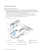
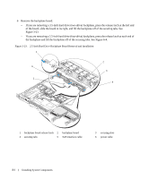
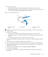
4 If applicable, remove the expansion card from the riser. 5 Press the release latch(es) on the riser board and lift the riser board straight up from the system board. See Figure 3-22. The left riser board has two release latches; the center riser board has one latch. Installing an Expansion-Card Riser CAUTION: Many repairs may only be done by a certified service technician. You should only perform troubleshooting and simple repairs as authorized in your product documentation, or as directed by the online or telephone service and support team. Damage due to servicing that is not authorized by Dell is not covered by your warranty. Read and follow the safety instructions that came with the product. 1 Align the riser board with the alignment pins on the system board, then lower the board onto the pins. 2 Press down on the riser board until the edge connector(s) on the board is (are) fully seated in the riser board connector on the system board. See Figure 3-22. 3 If applicable, install the expansion card in the expansion-card slot. 4 Close the system. See "Opening and Closing the System" on page 46. 5 Replace the bezel. See "Removing and Replacing the Front Bezel" on page 45. 6 Reconnect your system and peripherals to their electrical outlets, and turn on the system. Backplane Board Removing the Backplane Board CAUTION: Many repairs may only be done by a certified service technician. You should only perform troubleshooting and simple repairs as authorized in your product documentation, or as directed by the online or telephone service and support team. Damage due to servicing that is not authorized by Dell is not covered by your warranty. Read and follow the safety instructions that came with the product. The removal procedure varies slightly, depending on which backplane board you have in your system. 1 If applicable, remove the bezel. See "Removing and Replacing the Front Bezel" on page 45. 2 Turn off the system and attached peripherals, and disconnect the system from the electrical outlet. 3 Open the system. See "Opening and Closing the System" on page 46. 4 Remove the hard drives. NOTICE: To properly reinstall the hard drives, ensure that you record which hard drive you remove from which bay. 5 Disconnect the SAS cable and power cable from the backplane. - If you are removing a 3.5-inch hard drive (two-drive) backplane, see Figure 3-23. - If you are removing a 2.5-inch hard drive (four-drive) backplane, see Figure 6-4. Installing System Components 83
-
 1
1 -
2
-
3
-
4
-
5
-
6
-
7
-
8
-
9
-
10
-
11
-
12
-
13
-
14
-
15
-
16
-
17
-
18
-
19
-
20
-
21
-
22
-
23
-
24
-
25
-
26
-
27
-
28
-
29
-
30
-
31
-
32
-
33
-
34
-
35
-
36
-
37
-
38
-
39
-
40
-
41
-
42
-
43
-
44
-
45
-
46
-
47
-
48
-
49
-
50
-
51
-
52
-
53
-
54
-
55
-
56
-
57
-
58
-
59
-
60
-
61
-
62
-
63
-
64
-
65
-
66
-
67
-
68
-
69
-
70
-
71
-
72
-
73
-
74
-
75
-
76
-
77
-
 78
78 -
 79
79 -
 80
80 -
 81
81 -
 82
82 -
 83
83 -
 84
84 -
 85
85 -
 86
86 -
 87
87 -
 88
88 -
89
-
90
-
91
-
92
-
93
-
94
-
95
-
96
-
97
-
98
-
99
-
100
-
101
-
102
-
103
-
104
-
105
-
106
-
107
-
108
-
109
-
110
-
111
-
112
-
113
-
114
-
115
-
116
-
117
-
118
-
119
-
120
-
121
-
122
-
123
-
124
-
125
-
126
-
127
-
128
-
129
-
130
-
131
-
132
-
133
-
134
-
135
-
136
-
137
-
138
-
139
-
140
-
141
-
142
-
143
-
144
-
145
-
146
-
147
-
148
-
149
-
150
-
151
-
152
-
153
-
154
-
155
-
156
-
157
-
158
-
159
-
160
 |
 |