Dell PowerEdge 1950 Hardware Owner's Manual (PDF) - Page 85
Installing the Backplane Board, Sideplane Board, Removing the Sideplane Board
 |
View all Dell PowerEdge 1950 manuals
Add to My Manuals
Save this manual to your list of manuals |
Page 85 highlights
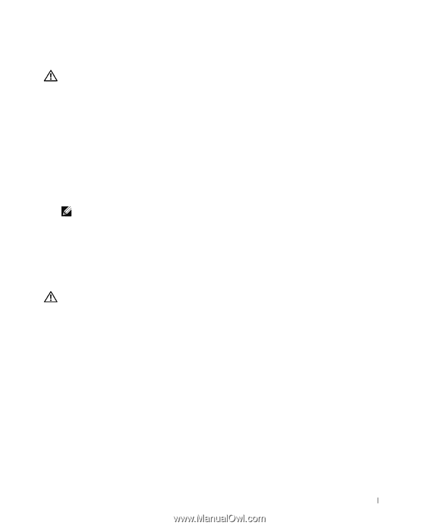
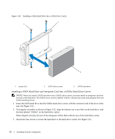
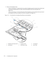
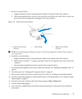
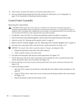
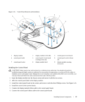
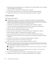
Installing the Backplane Board CAUTION: Many repairs may only be done by a certified service technician. You should only perform troubleshooting and simple repairs as authorized in your product documentation, or as directed by the online or telephone service and support team. Damage due to servicing that is not authorized by Dell is not covered by your warranty. Read and follow the safety instructions that came with the product. 1 Replace the backplane board: - If you are installing a 3.5-inch hard drive (two-drive) backplane, fit the board onto the securing tabs, press the release latch at the left end of the board and slide the board to its left. See Figure 3-23. - If you are installing a 2.5-inch hard drive (four-drive) backplane, fit the board onto the securing tabs on the back of the drive cage and slide the board downwards until the release latch at each end of the backplane clicks into place. See Figure 6-4. 2 Connect the SAS cable and power cable to the backplane connectors. 3 Reinstall the hard drives. NOTE: Reinstall the hard drives in the same drive bays from which they were removed. 4 Close the system. 5 If applicable, replace the bezel. Sideplane Board Removing the Sideplane Board CAUTION: Many repairs may only be done by a certified service technician. You should only perform troubleshooting and simple repairs as authorized in your product documentation, or as directed by the online or telephone service and support team. Damage due to servicing that is not authorized by Dell is not covered by your warranty. Read and follow the safety instructions that came with the product. 1 If applicable, remove the bezel. See "Removing and Replacing the Front Bezel" on page 45. 2 Turn off the system and attached peripherals, and disconnect the system from the electrical outlet. 3 Open the system. See "Opening and Closing the System" on page 46. 4 Remove the SAS controller daughter card. See "Removing a SAS Controller Daughter Card" on page 56. 5 Disconnect the control panel cable and optical drive cable (if applicable) from the sideplane. See Figure 6-8. 6 Press inward on the two sideplane release latches marked in blue and lift the sideplane up and away from the system board. Installing System Components 85
-
 1
1 -
2
-
3
-
4
-
5
-
6
-
7
-
8
-
9
-
10
-
11
-
12
-
13
-
14
-
15
-
16
-
17
-
18
-
19
-
20
-
21
-
22
-
23
-
24
-
25
-
26
-
27
-
28
-
29
-
30
-
31
-
32
-
33
-
34
-
35
-
36
-
37
-
38
-
39
-
40
-
41
-
42
-
43
-
44
-
45
-
46
-
47
-
48
-
49
-
50
-
51
-
52
-
53
-
54
-
55
-
56
-
57
-
58
-
59
-
60
-
61
-
62
-
63
-
64
-
65
-
66
-
67
-
68
-
69
-
70
-
71
-
72
-
73
-
74
-
75
-
76
-
77
-
78
-
79
-
 80
80 -
 81
81 -
 82
82 -
 83
83 -
 84
84 -
 85
85 -
 86
86 -
 87
87 -
 88
88 -
 89
89 -
 90
90 -
91
-
92
-
93
-
94
-
95
-
96
-
97
-
98
-
99
-
100
-
101
-
102
-
103
-
104
-
105
-
106
-
107
-
108
-
109
-
110
-
111
-
112
-
113
-
114
-
115
-
116
-
117
-
118
-
119
-
120
-
121
-
122
-
123
-
124
-
125
-
126
-
127
-
128
-
129
-
130
-
131
-
132
-
133
-
134
-
135
-
136
-
137
-
138
-
139
-
140
-
141
-
142
-
143
-
144
-
145
-
146
-
147
-
148
-
149
-
150
-
151
-
152
-
153
-
154
-
155
-
156
-
157
-
158
-
159
-
160
 |
 |