HP Designjet 250c Service Manual - Page 101
right side of the axial bias plate., Replace the overdrive clips underneath
 |
View all HP Designjet 250c manuals
Add to My Manuals
Save this manual to your list of manuals |
Page 101 highlights
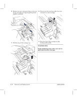
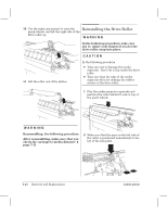
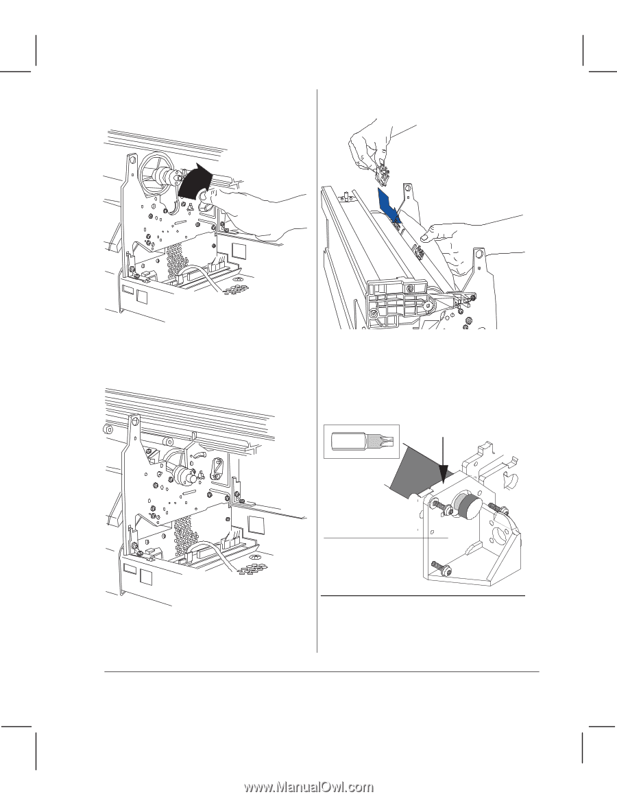
3 Use the right cam journal to lift the pinchĆwheels, and let the roller drop into place. 5 Replace the overdrive clips underneath the media separator. 4 Ensure that the bearing assembly at the right end of the drive roller is seated in the right sideplate and completely on the right side of the axial bias plate. 6 Replace the media mount. Press down on the media mount as you replace the three screws. This is to ensure correct spacing between the drive roller and the cartridge nozzles. Torx-20 Press down here as you tighten screws MediaĆmotor mount C4699Ć90000 Calibration: Perform the accuracy calibration after reassembling the plotter. (Details ' chapter 7.) Removal and Replacement 6Ć43
-
 1
1 -
2
-
3
-
4
-
5
-
6
-
7
-
8
-
9
-
10
-
11
-
12
-
13
-
14
-
15
-
16
-
17
-
18
-
19
-
20
-
21
-
22
-
23
-
24
-
25
-
26
-
27
-
28
-
29
-
30
-
31
-
32
-
33
-
34
-
35
-
36
-
37
-
38
-
39
-
40
-
41
-
42
-
43
-
44
-
45
-
46
-
47
-
48
-
49
-
50
-
51
-
52
-
53
-
54
-
55
-
56
-
57
-
58
-
59
-
60
-
61
-
62
-
63
-
64
-
65
-
66
-
67
-
68
-
69
-
70
-
71
-
72
-
73
-
74
-
75
-
76
-
77
-
78
-
79
-
80
-
81
-
82
-
83
-
84
-
85
-
86
-
87
-
88
-
89
-
90
-
91
-
92
-
93
-
94
-
95
-
 96
96 -
 97
97 -
 98
98 -
 99
99 -
 100
100 -
 101
101 -
 102
102 -
 103
103 -
 104
104 -
 105
105 -
 106
106 -
107
-
108
-
109
-
110
-
111
-
112
-
113
-
114
-
115
-
116
-
117
-
118
-
119
-
120
-
121
-
122
-
123
-
124
-
125
-
126
-
127
-
128
-
129
-
130
-
131
-
132
-
133
-
134
-
135
-
136
-
137
-
138
-
139
-
140
-
141
-
142
-
143
-
144
-
145
-
146
-
147
-
148
-
149
-
150
-
151
-
152
-
153
-
154
-
155
-
156
-
157
-
158
-
159
-
160
-
161
-
162
-
163
-
164
-
165
-
166
-
167
-
168
-
169
-
170
-
171
-
172
-
173
-
174
-
175
-
176
-
177
-
178
-
179
-
180
-
181
-
182
-
183
-
184
-
185
-
186
-
187
-
188
-
189
-
190
-
191
-
192
-
193
-
194
-
195
-
196
-
197
-
198
-
199
-
200
-
201
-
202
-
203
-
204
-
205
-
206
-
207
-
208
-
209
-
210
-
211
-
212
-
213
-
214
-
215
-
216
-
217
-
218
-
219
-
220
-
221
-
222
-
223
-
224
-
225
-
226
-
227
-
228
-
229
-
230
-
231
-
232
-
233
-
234
-
235
-
236
-
237
-
238
-
239
-
240
-
241
-
242
-
243
-
244
-
245
-
246
-
247
-
248
-
249
-
250
-
251
-
252
-
253
-
254
-
255
-
256
-
257
-
258
-
259
-
260
-
261
-
262
-
263
-
264
-
265
-
266
-
267
-
268
 |
 |
6Ć43
Removal and Replacement
C4699Ć90000
3
Use the right cam journal to lift the
pinchĆwheels, and let the roller drop into
place.
4
Ensure that the bearing assembly at the
right end of the drive roller is seated in
the right sideplate and completely on the
right side of the axial bias plate.
5
Replace the overdrive clips underneath
the media separator.
6
Replace the media mount.
Press down on the media mount as you
replace the three screws. This is to ensure
correct spacing between the drive roller
and the cartridge nozzles.
Press down here as
you tighten screws
MediaĆmotor mount
Torx-20
Calibration:
Perform the accuracy
calibration after reassembling the plotter.
(Details
'
chapter 7.)