HP Designjet 250c Service Manual - Page 88
Remove the screw from the plastic bail, Pull the bail gear assembly out from
 |
View all HP Designjet 250c manuals
Add to My Manuals
Save this manual to your list of manuals |
Page 88 highlights
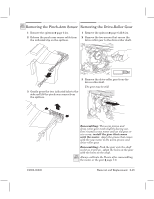
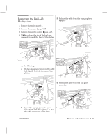
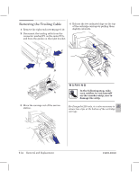
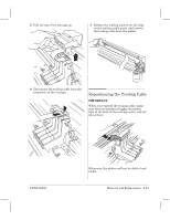
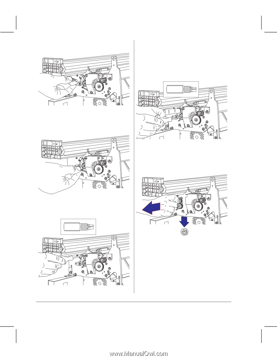
7 Remove the engaging lever. 10 Remove the screw from the plastic bail gear. You may need to hold the bail cam steady inside the sideĆplate at the same time. You can access the cam through the hole underneath the sideĆplate. Torx-15 8 Remove the spring from the bailĆgear assembly. 11 Pull the bail gear assembly out from the plotter. The cam falls to the floor of the plotter. 9 Loosen the screw from the top of the bailĆgear assembly. Torx-8 6Ć30 Removal and Replacement C4699Ć90000
-
 1
1 -
2
-
3
-
4
-
5
-
6
-
7
-
8
-
9
-
10
-
11
-
12
-
13
-
14
-
15
-
16
-
17
-
18
-
19
-
20
-
21
-
22
-
23
-
24
-
25
-
26
-
27
-
28
-
29
-
30
-
31
-
32
-
33
-
34
-
35
-
36
-
37
-
38
-
39
-
40
-
41
-
42
-
43
-
44
-
45
-
46
-
47
-
48
-
49
-
50
-
51
-
52
-
53
-
54
-
55
-
56
-
57
-
58
-
59
-
60
-
61
-
62
-
63
-
64
-
65
-
66
-
67
-
68
-
69
-
70
-
71
-
72
-
73
-
74
-
75
-
76
-
77
-
78
-
79
-
80
-
81
-
82
-
 83
83 -
 84
84 -
 85
85 -
 86
86 -
 87
87 -
 88
88 -
 89
89 -
 90
90 -
 91
91 -
 92
92 -
 93
93 -
94
-
95
-
96
-
97
-
98
-
99
-
100
-
101
-
102
-
103
-
104
-
105
-
106
-
107
-
108
-
109
-
110
-
111
-
112
-
113
-
114
-
115
-
116
-
117
-
118
-
119
-
120
-
121
-
122
-
123
-
124
-
125
-
126
-
127
-
128
-
129
-
130
-
131
-
132
-
133
-
134
-
135
-
136
-
137
-
138
-
139
-
140
-
141
-
142
-
143
-
144
-
145
-
146
-
147
-
148
-
149
-
150
-
151
-
152
-
153
-
154
-
155
-
156
-
157
-
158
-
159
-
160
-
161
-
162
-
163
-
164
-
165
-
166
-
167
-
168
-
169
-
170
-
171
-
172
-
173
-
174
-
175
-
176
-
177
-
178
-
179
-
180
-
181
-
182
-
183
-
184
-
185
-
186
-
187
-
188
-
189
-
190
-
191
-
192
-
193
-
194
-
195
-
196
-
197
-
198
-
199
-
200
-
201
-
202
-
203
-
204
-
205
-
206
-
207
-
208
-
209
-
210
-
211
-
212
-
213
-
214
-
215
-
216
-
217
-
218
-
219
-
220
-
221
-
222
-
223
-
224
-
225
-
226
-
227
-
228
-
229
-
230
-
231
-
232
-
233
-
234
-
235
-
236
-
237
-
238
-
239
-
240
-
241
-
242
-
243
-
244
-
245
-
246
-
247
-
248
-
249
-
250
-
251
-
252
-
253
-
254
-
255
-
256
-
257
-
258
-
259
-
260
-
261
-
262
-
263
-
264
-
265
-
266
-
267
-
268
 |
 |
6Ć30
Removal and Replacement
C4699Ć90000
7
Remove the engaging lever.
8
Remove the spring from the bailĆgear
assembly.
9
Loosen the screw from the top of the
bailĆgear assembly.
Torx-8
10
Remove the screw from the plastic bail
gear.
You may need to hold the bail cam steady
inside the sideĆplate at the same time. You
can access the cam through the hole
underneath the sideĆplate.
Torx-15
11
Pull the bail gear assembly out from the
plotter.
The cam falls to the floor of the plotter.