HP Designjet 250c Service Manual - Page 136
PowerĆOn, Self Test and Initialization
 |
View all HP Designjet 250c manuals
Add to My Manuals
Save this manual to your list of manuals |
Page 136 highlights
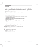
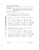
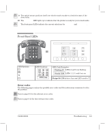
PowerĆOn The plotters automatically perform a series of internal self tests and mechanical initialization sequences whenever the user switches the plotter on. These are completed after about 30 seconds. If a failure occurs, an error is indicated on the frontĆpanel LEDs. You can perform a failure analysis by interpreting the LED error code. (Details ' later in this chapter.) Self Test and Initialization The powerĆon self test and initialization procedure does the following: 1 Initializes the servo processor. 2 Initializes the main processor. 3 Tests communication between the main processor and the servo processor. 4 Tests the EEROM checksum. 5 Tests the servoĆprocessor transfer buffer and interrupt tracking. 6 Tests the ROM checksum. 7 Causes the main processor to initialize certain firmware modules. 8 Performs a subset of the electrical service test. 9 Checks the cover sensor. If the cover is open, nothing further happens until you close it. 10 Initializes the carriage axis (YĆaxis). 330 350C 11 Uses the mark encoder to check the start of the drive roller. 12 Ejects any loaded sheet. 330 350C Does not eject roll media if loaded. 13 Checks the media sensor. 14 Sets the plotter to accept media. 8Ć2 Troubleshooting C4699Ć90000
-
 1
1 -
2
-
3
-
4
-
5
-
6
-
7
-
8
-
9
-
10
-
11
-
12
-
13
-
14
-
15
-
16
-
17
-
18
-
19
-
20
-
21
-
22
-
23
-
24
-
25
-
26
-
27
-
28
-
29
-
30
-
31
-
32
-
33
-
34
-
35
-
36
-
37
-
38
-
39
-
40
-
41
-
42
-
43
-
44
-
45
-
46
-
47
-
48
-
49
-
50
-
51
-
52
-
53
-
54
-
55
-
56
-
57
-
58
-
59
-
60
-
61
-
62
-
63
-
64
-
65
-
66
-
67
-
68
-
69
-
70
-
71
-
72
-
73
-
74
-
75
-
76
-
77
-
78
-
79
-
80
-
81
-
82
-
83
-
84
-
85
-
86
-
87
-
88
-
89
-
90
-
91
-
92
-
93
-
94
-
95
-
96
-
97
-
98
-
99
-
100
-
101
-
102
-
103
-
104
-
105
-
106
-
107
-
108
-
109
-
110
-
111
-
112
-
113
-
114
-
115
-
116
-
117
-
118
-
119
-
120
-
121
-
122
-
123
-
124
-
125
-
126
-
127
-
128
-
129
-
130
-
 131
131 -
 132
132 -
 133
133 -
 134
134 -
 135
135 -
 136
136 -
 137
137 -
 138
138 -
 139
139 -
 140
140 -
 141
141 -
142
-
143
-
144
-
145
-
146
-
147
-
148
-
149
-
150
-
151
-
152
-
153
-
154
-
155
-
156
-
157
-
158
-
159
-
160
-
161
-
162
-
163
-
164
-
165
-
166
-
167
-
168
-
169
-
170
-
171
-
172
-
173
-
174
-
175
-
176
-
177
-
178
-
179
-
180
-
181
-
182
-
183
-
184
-
185
-
186
-
187
-
188
-
189
-
190
-
191
-
192
-
193
-
194
-
195
-
196
-
197
-
198
-
199
-
200
-
201
-
202
-
203
-
204
-
205
-
206
-
207
-
208
-
209
-
210
-
211
-
212
-
213
-
214
-
215
-
216
-
217
-
218
-
219
-
220
-
221
-
222
-
223
-
224
-
225
-
226
-
227
-
228
-
229
-
230
-
231
-
232
-
233
-
234
-
235
-
236
-
237
-
238
-
239
-
240
-
241
-
242
-
243
-
244
-
245
-
246
-
247
-
248
-
249
-
250
-
251
-
252
-
253
-
254
-
255
-
256
-
257
-
258
-
259
-
260
-
261
-
262
-
263
-
264
-
265
-
266
-
267
-
268
 |
 |