HP Designjet 250c Service Manual - Page 56
EEROM, Input/Output Interfaces, HP JetDirect EX, Network Connections, Accessories
 |
View all HP Designjet 250c manuals
Add to My Manuals
Save this manual to your list of manuals |
Page 56 highlights
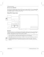
ROM The plotter firmware code is contained on either an inĆbuilt masked ROM (soldered to the main PCA) or a flash ROM SIMM (installed in the innerĆmost socket at the back of the plotter). If both are present, the plotter recognizes the code on the ROM SIMM instead of that on the inĆbuilt ROM. The powerĆon LED sequence tells you whether the plotter is using code from inĆbuilt ROM or from a ROM SIMM. (Details ' page 8Ć3.) To find out the firmwareĆcode revision level that the plotter is using, print a user setup sheet or a service configuration plot. RAM The plotters have a standard four megabytes of onĆboard RAM. They also have one RAMĆ expansion socket, which can hold an optional 4Ć, 8Ć, 16Ć or 32Ć megabyte DRAM SIMM. The socket is the outerĆmost one at the back of the plotter. EEROM EEROM is used as nonvolatile storage for calibration and configuration data. Useful information from the EEROM is printed on the service configuration plot ' page 8Ć49 (DesignJet 230/250C) or page 8Ć50 (DesignJet 330/350C). The EEROM is soldered to the Main PCA in both new and rebuilt electronic modules. If you clear the EEROM or replace the electronics module, perform all calibrations. Also note that the factory spittoon value on the cleared or new EEROM is 0%. Keep in mind that the value printed on the service configuration plot may greatly underestimate the amount of ink in the spittoon. Future PCĆbased plotter diagnostics will enable you to download information from the old EEROM and upload it to the new EEROM. (Clearing the EEROM ' page 8Ć54/8Ć55.) Input/Output Interfaces Like the DesignJet 220, the plotters have both a parallel (BiĆTronics) and a serial (RSĆ232ĆC) interface. Unlike the DesignJet 650C, they have no modular input/output (MIO). You can connect the plotters to a network by means of an HP JetDirect EX or HP JetDirect EX Plus3 external print server. (See also ' chapter 1, w Network Connections, and chapter 10, w Accessories.) BiĆTronics In addition to the operating modes of the DesignJet 220, the BiĆTronics interfaces of the DesignJet 230 and 250C and DesignJet 330 and 350C feature the extendedĆcapabilityĆport (ECP) forward and reverse operating modes, providing for faster communication. RSĆ232ĆC The supported baudrates are 1200, 2400, 4800, 9600, 19200 and 38400, with eight bits and no parity, or seven bits with either odd or even parity. Mark parity is not supported. Both XON/XOFF and DTR handshaking are supported. ENQ/ACK handshake is not supported. 5Ć14 Functional Overview C4699Ć90000
-
 1
1 -
2
-
3
-
4
-
5
-
6
-
7
-
8
-
9
-
10
-
11
-
12
-
13
-
14
-
15
-
16
-
17
-
18
-
19
-
20
-
21
-
22
-
23
-
24
-
25
-
26
-
27
-
28
-
29
-
30
-
31
-
32
-
33
-
34
-
35
-
36
-
37
-
38
-
39
-
40
-
41
-
42
-
43
-
44
-
45
-
46
-
47
-
48
-
49
-
50
-
 51
51 -
 52
52 -
 53
53 -
 54
54 -
 55
55 -
 56
56 -
 57
57 -
 58
58 -
 59
59 -
 60
60 -
 61
61 -
62
-
63
-
64
-
65
-
66
-
67
-
68
-
69
-
70
-
71
-
72
-
73
-
74
-
75
-
76
-
77
-
78
-
79
-
80
-
81
-
82
-
83
-
84
-
85
-
86
-
87
-
88
-
89
-
90
-
91
-
92
-
93
-
94
-
95
-
96
-
97
-
98
-
99
-
100
-
101
-
102
-
103
-
104
-
105
-
106
-
107
-
108
-
109
-
110
-
111
-
112
-
113
-
114
-
115
-
116
-
117
-
118
-
119
-
120
-
121
-
122
-
123
-
124
-
125
-
126
-
127
-
128
-
129
-
130
-
131
-
132
-
133
-
134
-
135
-
136
-
137
-
138
-
139
-
140
-
141
-
142
-
143
-
144
-
145
-
146
-
147
-
148
-
149
-
150
-
151
-
152
-
153
-
154
-
155
-
156
-
157
-
158
-
159
-
160
-
161
-
162
-
163
-
164
-
165
-
166
-
167
-
168
-
169
-
170
-
171
-
172
-
173
-
174
-
175
-
176
-
177
-
178
-
179
-
180
-
181
-
182
-
183
-
184
-
185
-
186
-
187
-
188
-
189
-
190
-
191
-
192
-
193
-
194
-
195
-
196
-
197
-
198
-
199
-
200
-
201
-
202
-
203
-
204
-
205
-
206
-
207
-
208
-
209
-
210
-
211
-
212
-
213
-
214
-
215
-
216
-
217
-
218
-
219
-
220
-
221
-
222
-
223
-
224
-
225
-
226
-
227
-
228
-
229
-
230
-
231
-
232
-
233
-
234
-
235
-
236
-
237
-
238
-
239
-
240
-
241
-
242
-
243
-
244
-
245
-
246
-
247
-
248
-
249
-
250
-
251
-
252
-
253
-
254
-
255
-
256
-
257
-
258
-
259
-
260
-
261
-
262
-
263
-
264
-
265
-
266
-
267
-
268
 |
 |