HP Designjet 250c Service Manual - Page 91
Removing the Back Cover, Pull the bottom of the cover slightly back
 |
View all HP Designjet 250c manuals
Add to My Manuals
Save this manual to your list of manuals |
Page 91 highlights
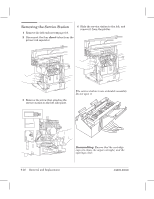
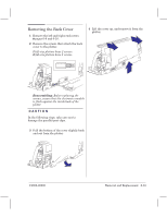
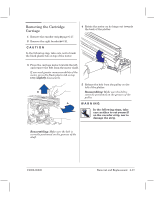
Removing the Back Cover 1 Remove the left and right endĆcovers ' pages 6Ć9 and 6Ć10. 2 Remove the screws that attach the back cover to the plotter. D/A1Ćsize plotters have 2 screws. E/A0Ćsize plotters have 3 screws. 4 Lift the cover up, and remove it from the plotter. Torx-20 Reassembling: Before replacing the screws, ensure that the electronics module is flush against the inside back of the plotter. CAUTION In the following steps, take care not to damage the parallelĆport clips. 3 Pull the bottom of the cover slightly back and out from the plotter. C4699Ć90000 Removal and Replacement 6Ć33
-
 1
1 -
2
-
3
-
4
-
5
-
6
-
7
-
8
-
9
-
10
-
11
-
12
-
13
-
14
-
15
-
16
-
17
-
18
-
19
-
20
-
21
-
22
-
23
-
24
-
25
-
26
-
27
-
28
-
29
-
30
-
31
-
32
-
33
-
34
-
35
-
36
-
37
-
38
-
39
-
40
-
41
-
42
-
43
-
44
-
45
-
46
-
47
-
48
-
49
-
50
-
51
-
52
-
53
-
54
-
55
-
56
-
57
-
58
-
59
-
60
-
61
-
62
-
63
-
64
-
65
-
66
-
67
-
68
-
69
-
70
-
71
-
72
-
73
-
74
-
75
-
76
-
77
-
78
-
79
-
80
-
81
-
82
-
83
-
84
-
85
-
 86
86 -
 87
87 -
 88
88 -
 89
89 -
 90
90 -
 91
91 -
 92
92 -
 93
93 -
 94
94 -
 95
95 -
 96
96 -
97
-
98
-
99
-
100
-
101
-
102
-
103
-
104
-
105
-
106
-
107
-
108
-
109
-
110
-
111
-
112
-
113
-
114
-
115
-
116
-
117
-
118
-
119
-
120
-
121
-
122
-
123
-
124
-
125
-
126
-
127
-
128
-
129
-
130
-
131
-
132
-
133
-
134
-
135
-
136
-
137
-
138
-
139
-
140
-
141
-
142
-
143
-
144
-
145
-
146
-
147
-
148
-
149
-
150
-
151
-
152
-
153
-
154
-
155
-
156
-
157
-
158
-
159
-
160
-
161
-
162
-
163
-
164
-
165
-
166
-
167
-
168
-
169
-
170
-
171
-
172
-
173
-
174
-
175
-
176
-
177
-
178
-
179
-
180
-
181
-
182
-
183
-
184
-
185
-
186
-
187
-
188
-
189
-
190
-
191
-
192
-
193
-
194
-
195
-
196
-
197
-
198
-
199
-
200
-
201
-
202
-
203
-
204
-
205
-
206
-
207
-
208
-
209
-
210
-
211
-
212
-
213
-
214
-
215
-
216
-
217
-
218
-
219
-
220
-
221
-
222
-
223
-
224
-
225
-
226
-
227
-
228
-
229
-
230
-
231
-
232
-
233
-
234
-
235
-
236
-
237
-
238
-
239
-
240
-
241
-
242
-
243
-
244
-
245
-
246
-
247
-
248
-
249
-
250
-
251
-
252
-
253
-
254
-
255
-
256
-
257
-
258
-
259
-
260
-
261
-
262
-
263
-
264
-
265
-
266
-
267
-
268
 |
 |
6Ć33
Removal and Replacement
C4699Ć90000
Removing the Back Cover
1
Remove the left and right endĆcovers
'
pages 6Ć9 and 6Ć10.
2
Remove the screws that attach the back
cover to the plotter.
D/A1Ćsize plotters have 2 screws.
E/A0Ćsize plotters have 3 screws.
Torx-20
Reassembling:
Before replacing the
screws, ensure that the electronics module
is flush against the inside back of the
plotter.
CAUTION
In the following steps, take care not to
damage the parallelĆport clips.
3
Pull the bottom of the cover slightly back
and out from the plotter.
4
Lift the cover up, and remove it from the
plotter.