HP Designjet 250c Service Manual - Page 103
Reinstalling the PinchĆArm Lift, Mechanism, journal, tighten its nut just to the point
 |
View all HP Designjet 250c manuals
Add to My Manuals
Save this manual to your list of manuals |
Page 103 highlights
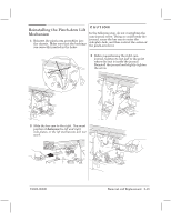
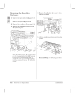
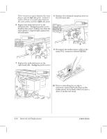
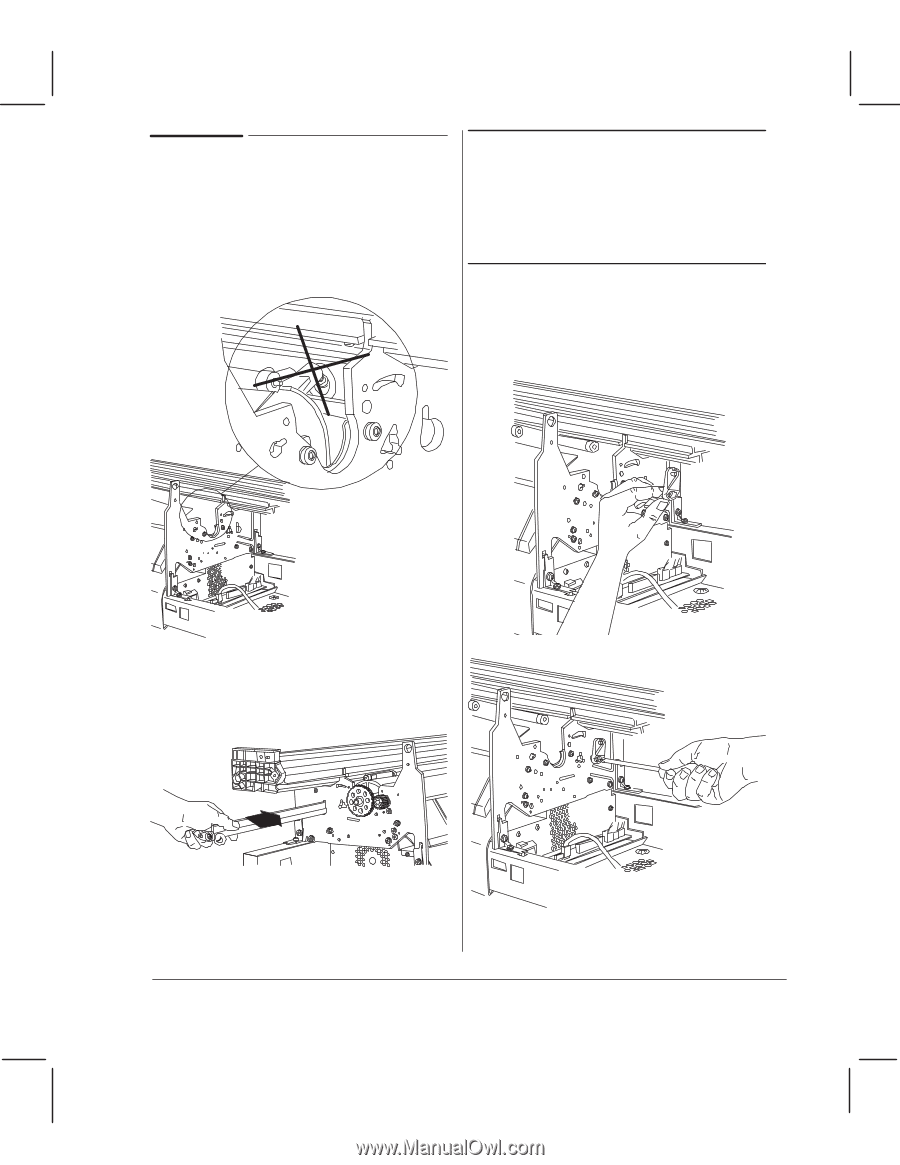
Reinstalling the PinchĆArm Lift Mechanism 1 Reinsert the pinchĆarm assemblies into the chassis. Make sure that the bushings are correctly inserted in the holes. CAUTION In the following step, do not overtighten the camĆjournal screw. Doing so could break the journal, cause the bar cam to enter the sideĆplate hole, and thus restrict the action of the pinchĆarm lever. 3 Before repositioning the right cam journal, tighten its nut just to the point where the nut is inside the journal. Reinstall the journal and slightly tighten the screw. 2 Slide the bar cam to the right. You must position it between the left and right sideĆplates, or the lift mechanism will not work. C4699Ć90000 Removal and Replacement 6Ć45
-
 1
1 -
2
-
3
-
4
-
5
-
6
-
7
-
8
-
9
-
10
-
11
-
12
-
13
-
14
-
15
-
16
-
17
-
18
-
19
-
20
-
21
-
22
-
23
-
24
-
25
-
26
-
27
-
28
-
29
-
30
-
31
-
32
-
33
-
34
-
35
-
36
-
37
-
38
-
39
-
40
-
41
-
42
-
43
-
44
-
45
-
46
-
47
-
48
-
49
-
50
-
51
-
52
-
53
-
54
-
55
-
56
-
57
-
58
-
59
-
60
-
61
-
62
-
63
-
64
-
65
-
66
-
67
-
68
-
69
-
70
-
71
-
72
-
73
-
74
-
75
-
76
-
77
-
78
-
79
-
80
-
81
-
82
-
83
-
84
-
85
-
86
-
87
-
88
-
89
-
90
-
91
-
92
-
93
-
94
-
95
-
96
-
97
-
 98
98 -
 99
99 -
 100
100 -
 101
101 -
 102
102 -
 103
103 -
 104
104 -
 105
105 -
 106
106 -
 107
107 -
 108
108 -
109
-
110
-
111
-
112
-
113
-
114
-
115
-
116
-
117
-
118
-
119
-
120
-
121
-
122
-
123
-
124
-
125
-
126
-
127
-
128
-
129
-
130
-
131
-
132
-
133
-
134
-
135
-
136
-
137
-
138
-
139
-
140
-
141
-
142
-
143
-
144
-
145
-
146
-
147
-
148
-
149
-
150
-
151
-
152
-
153
-
154
-
155
-
156
-
157
-
158
-
159
-
160
-
161
-
162
-
163
-
164
-
165
-
166
-
167
-
168
-
169
-
170
-
171
-
172
-
173
-
174
-
175
-
176
-
177
-
178
-
179
-
180
-
181
-
182
-
183
-
184
-
185
-
186
-
187
-
188
-
189
-
190
-
191
-
192
-
193
-
194
-
195
-
196
-
197
-
198
-
199
-
200
-
201
-
202
-
203
-
204
-
205
-
206
-
207
-
208
-
209
-
210
-
211
-
212
-
213
-
214
-
215
-
216
-
217
-
218
-
219
-
220
-
221
-
222
-
223
-
224
-
225
-
226
-
227
-
228
-
229
-
230
-
231
-
232
-
233
-
234
-
235
-
236
-
237
-
238
-
239
-
240
-
241
-
242
-
243
-
244
-
245
-
246
-
247
-
248
-
249
-
250
-
251
-
252
-
253
-
254
-
255
-
256
-
257
-
258
-
259
-
260
-
261
-
262
-
263
-
264
-
265
-
266
-
267
-
268
 |
 |
6Ć45
Removal and Replacement
C4699Ć90000
Reinstalling the PinchĆArm Lift
Mechanism
1
Reinsert the pinchĆarm assemblies into
the chassis. Make sure that the bushings
are correctly inserted in the holes.
2
Slide the bar cam to the right. You must
position it
between
the left and right
sideĆplates, or the lift mechanism will not
work.
CAUTION
In the following step, do not overtighten the
camĆjournal screw. Doing so could break the
journal, cause the bar cam to enter the
sideĆplate hole, and thus restrict the action of
the pinchĆarm lever.
3
Before repositioning the right cam
journal, tighten its nut just to the point
where the nut is inside the journal.
Reinstall the journal and slightly tighten
the screw.