HP Designjet 250c Service Manual - Page 72
Reassembling, Connector, Cable, Calibrations, installed from the old module and install
 |
View all HP Designjet 250c manuals
Add to My Manuals
Save this manual to your list of manuals |
Page 72 highlights
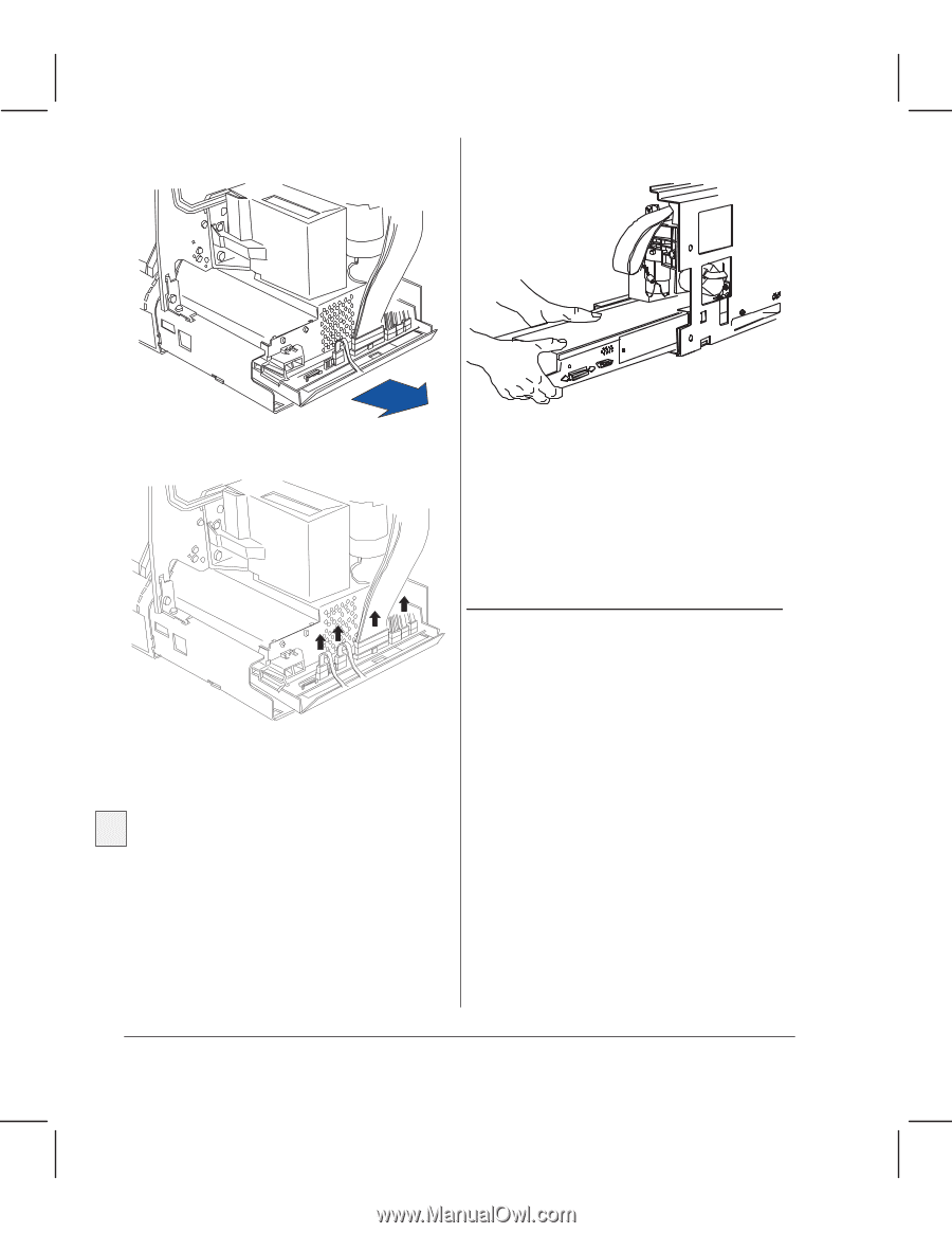
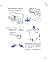
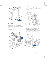
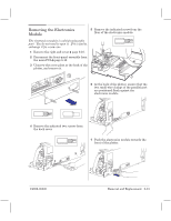
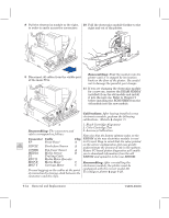
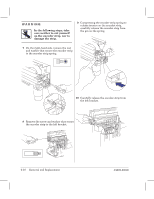
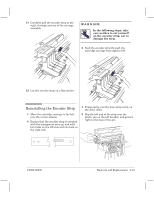
8 Pull the electronics module to the right, 10 Pull the electronics module further to the in order to easily access the connectors. right and out of the plotter. 9 Disconnect all cables from the visible part of the main PCA. Reassembling: Slide the module into the plotter until it is stopped by its location hook on the floor of the plotter. Be careful not to damage the parallelĆport clamps. 11 If you are changing the electronics module for a new one, remove the DRAM SIMM(if installed) from the old module and install it into the new one. Refer to Chapter 9 C before installing the ROM SIMM from the old module into the new module. Calibrations: After having installed a new B electronics module, perform the following calibrations. (Details ' chapter 7.) A 1. Black Cartridge Alignment 2. Color Cartridge Test Reassembling: The connectors and 3. Accuracy Calibration cables correspond as follows: Note also that the factory spittoon value on the Connector Cable 330 350C FP PINCH Front Panel PinchĆArm Sensor COVER TopĆCover Sensor Clip EEROM of the new electronics module is reset A to 0% used. Keep in mind that the value printed A on the service configuration plot may greatly underestimate the amount of ink in the spittoon. A Future PCĆbased plotter diagnostics will enable MEDIA Media Sensor B you to download information from the old P1 Trailing Cable EEROM and upload it to the new EEROM. ENC X Media Motor Encoder MOT X MOT Y Media Motor Carriage Motor C Reassembling: After reinstalling the C electronics module, the plotter must be Prevent tugging on the cables at the point of connection by leaving slack between the configured with the correct model ID. To configure plotter ' page 8Ć28. connectors and the clips. 6Ć14 Removal and Replacement C4699Ć90000
-
 1
1 -
2
-
3
-
4
-
5
-
6
-
7
-
8
-
9
-
10
-
11
-
12
-
13
-
14
-
15
-
16
-
17
-
18
-
19
-
20
-
21
-
22
-
23
-
24
-
25
-
26
-
27
-
28
-
29
-
30
-
31
-
32
-
33
-
34
-
35
-
36
-
37
-
38
-
39
-
40
-
41
-
42
-
43
-
44
-
45
-
46
-
47
-
48
-
49
-
50
-
51
-
52
-
53
-
54
-
55
-
56
-
57
-
58
-
59
-
60
-
61
-
62
-
63
-
64
-
65
-
66
-
 67
67 -
 68
68 -
 69
69 -
 70
70 -
 71
71 -
 72
72 -
 73
73 -
 74
74 -
 75
75 -
 76
76 -
 77
77 -
78
-
79
-
80
-
81
-
82
-
83
-
84
-
85
-
86
-
87
-
88
-
89
-
90
-
91
-
92
-
93
-
94
-
95
-
96
-
97
-
98
-
99
-
100
-
101
-
102
-
103
-
104
-
105
-
106
-
107
-
108
-
109
-
110
-
111
-
112
-
113
-
114
-
115
-
116
-
117
-
118
-
119
-
120
-
121
-
122
-
123
-
124
-
125
-
126
-
127
-
128
-
129
-
130
-
131
-
132
-
133
-
134
-
135
-
136
-
137
-
138
-
139
-
140
-
141
-
142
-
143
-
144
-
145
-
146
-
147
-
148
-
149
-
150
-
151
-
152
-
153
-
154
-
155
-
156
-
157
-
158
-
159
-
160
-
161
-
162
-
163
-
164
-
165
-
166
-
167
-
168
-
169
-
170
-
171
-
172
-
173
-
174
-
175
-
176
-
177
-
178
-
179
-
180
-
181
-
182
-
183
-
184
-
185
-
186
-
187
-
188
-
189
-
190
-
191
-
192
-
193
-
194
-
195
-
196
-
197
-
198
-
199
-
200
-
201
-
202
-
203
-
204
-
205
-
206
-
207
-
208
-
209
-
210
-
211
-
212
-
213
-
214
-
215
-
216
-
217
-
218
-
219
-
220
-
221
-
222
-
223
-
224
-
225
-
226
-
227
-
228
-
229
-
230
-
231
-
232
-
233
-
234
-
235
-
236
-
237
-
238
-
239
-
240
-
241
-
242
-
243
-
244
-
245
-
246
-
247
-
248
-
249
-
250
-
251
-
252
-
253
-
254
-
255
-
256
-
257
-
258
-
259
-
260
-
261
-
262
-
263
-
264
-
265
-
266
-
267
-
268
 |
 |