HP Designjet 250c Service Manual - Page 70
Disconnecting the FrontĆPanel, Assembly, release it from the clip on the side of
 |
View all HP Designjet 250c manuals
Add to My Manuals
Save this manual to your list of manuals |
Page 70 highlights
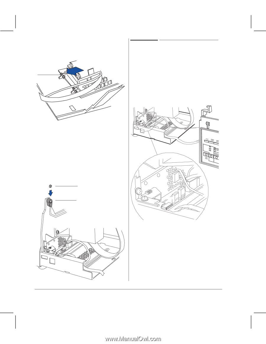
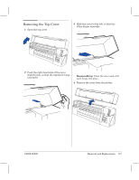
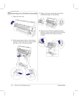
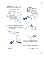
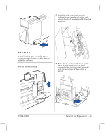
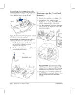
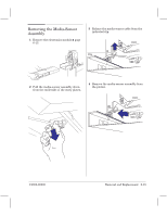
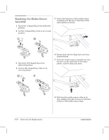
Reinstalling the frontĆpanel assembly: Insert the bottom of the assembly into the two indicated notches, inside the right endĆcover. Then firmly reinsert the top two tabs. Disconnecting the FrontĆPanel Assembly Notch 1 Remove the right endĆcover ' page 6Ć10. 2 On the main PCA, gently pull the frontĆpanel connector clamp (FP) to the right to release the flat, white cable. 3 Pull the cable easily out of the clamp, and release it from the clip on the side of the electronics module. Push the front panel from the outside, to check whether it is correctly installed. Reinstalling the right endĆcover: Before replacing the endĆcover, make sure that a The black plastic piece at the front end of the pinchĆarm linkage is correctly attached to the sideĆplate. b The lever nut is positioned inside the slot on the black plastic piece. Nut Black plastic piece COVER FP Reassembling: The contact part of the cable faces down. Prevent tugging of the cable at the point of connection by leaving slack between the connector and the clip. 4 Detach the topĆcoverĆsensor cable from the COVER connector, and release it from the clip on the side of the electronics module. 6Ć12 Removal and Replacement C4699Ć90000
-
 1
1 -
2
-
3
-
4
-
5
-
6
-
7
-
8
-
9
-
10
-
11
-
12
-
13
-
14
-
15
-
16
-
17
-
18
-
19
-
20
-
21
-
22
-
23
-
24
-
25
-
26
-
27
-
28
-
29
-
30
-
31
-
32
-
33
-
34
-
35
-
36
-
37
-
38
-
39
-
40
-
41
-
42
-
43
-
44
-
45
-
46
-
47
-
48
-
49
-
50
-
51
-
52
-
53
-
54
-
55
-
56
-
57
-
58
-
59
-
60
-
61
-
62
-
63
-
64
-
 65
65 -
 66
66 -
 67
67 -
 68
68 -
 69
69 -
 70
70 -
 71
71 -
 72
72 -
 73
73 -
 74
74 -
 75
75 -
76
-
77
-
78
-
79
-
80
-
81
-
82
-
83
-
84
-
85
-
86
-
87
-
88
-
89
-
90
-
91
-
92
-
93
-
94
-
95
-
96
-
97
-
98
-
99
-
100
-
101
-
102
-
103
-
104
-
105
-
106
-
107
-
108
-
109
-
110
-
111
-
112
-
113
-
114
-
115
-
116
-
117
-
118
-
119
-
120
-
121
-
122
-
123
-
124
-
125
-
126
-
127
-
128
-
129
-
130
-
131
-
132
-
133
-
134
-
135
-
136
-
137
-
138
-
139
-
140
-
141
-
142
-
143
-
144
-
145
-
146
-
147
-
148
-
149
-
150
-
151
-
152
-
153
-
154
-
155
-
156
-
157
-
158
-
159
-
160
-
161
-
162
-
163
-
164
-
165
-
166
-
167
-
168
-
169
-
170
-
171
-
172
-
173
-
174
-
175
-
176
-
177
-
178
-
179
-
180
-
181
-
182
-
183
-
184
-
185
-
186
-
187
-
188
-
189
-
190
-
191
-
192
-
193
-
194
-
195
-
196
-
197
-
198
-
199
-
200
-
201
-
202
-
203
-
204
-
205
-
206
-
207
-
208
-
209
-
210
-
211
-
212
-
213
-
214
-
215
-
216
-
217
-
218
-
219
-
220
-
221
-
222
-
223
-
224
-
225
-
226
-
227
-
228
-
229
-
230
-
231
-
232
-
233
-
234
-
235
-
236
-
237
-
238
-
239
-
240
-
241
-
242
-
243
-
244
-
245
-
246
-
247
-
248
-
249
-
250
-
251
-
252
-
253
-
254
-
255
-
256
-
257
-
258
-
259
-
260
-
261
-
262
-
263
-
264
-
265
-
266
-
267
-
268
 |
 |