Icom IC-7700 Instruction Manual
Icom IC-7700 Manual
 |
View all Icom IC-7700 manuals
Add to My Manuals
Save this manual to your list of manuals |
Icom IC-7700 manual content summary:
- Icom IC-7700 | Instruction Manual - Page 1
HF/50 MHz TRANSCEIVER i7700 Instruction Manual A-6612H-1EX-q Printed in Japan © 2008 Icom Inc. - Icom IC-7700 | Instruction Manual - Page 2
radio of choice. We hope you agree with Icom's philosophy of "technology first." Many hours of research and development went into the design of your IC-7700. D FEATURES ❍ Ultimate receiver performance: third-order intercept (IP3) of +40 dBm (HF bands only) ❍ Built-in Baudot RTTY and PSK31 modulator - Icom IC-7700 | Instruction Manual - Page 3
set the transceiver's RF output power to less than the linear amplifier's maximum input level, otherwise, the linear amplifier will be damaged. Use Icom microphones only (supplied or optional). Other manufacturers' microphones have different pin assignments, and connection to the IC-7700 may damage - Icom IC-7700 | Instruction Manual - Page 4
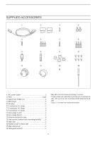
ACCESSORIES q w e r t y u i o !0 !1 !2 !3 !4 !5 !56 q AC power cable 1 w Feet 1 pair e Spare fuse (FGB 2 A 1 r RCA plugs 2 t DC plug differ from that shown according to version. † These screws are used when removing rack mounting handles. See p.2-3 for rack mounting handle - Icom IC-7700 | Instruction Manual - Page 5
-Icom linear amplifier 2-8 ■ Transverter jack information 2-9 ■ FSK and AFSK (SSTV) connections 2-9 ■ Microphone connector information 2-10 ■ Microphones (options 2-10 D SM-20 2-10 D HM-36 2-10 ■ Accessory connector information 2-11 BASIC OPERATIONS ■ When first applying power (CPU resetting - Icom IC-7700 | Instruction Manual - Page 6
for receive 4-4 D Convenient functions for transmit 4-5 D About CW reverse mode 4-5 D About CW pitch control 4-5 D CW side tone function 4-5 D APF (Audio Peak Filter) operation 4-6 ■ Electronic keyer functions 4-7 D Memory keyer screen 4-8 D Editing a memory keyer 4-9 D Contest number set - Icom IC-7700 | Instruction Manual - Page 7
Data mode (AFSK) operation 4-35 FUNCTIONS FOR RECEIVE ■ Spectrum scope screen 5-2 D Center mode 5-2 D Fixed mode 5-3 D Mini filter selection 5-13 D IF filter selection 5-13 D Filter passband width setting (except FM mode 5-13 D Roofing filter selection 5-14 D DSP filter shape 5-14 D Filter - Icom IC-7700 | Instruction Manual - Page 8
received audio memory 7-10 D Saving the TX memory 7-10 MEMORY OPERATION ■ Memory channels 8-2 ■ Memory channel selection 8-2 D Using the ∫ / √ keys 8-2 D Using SCANS ■ Scan types 9-2 ■ Preparation 9-2 ■ Voice squelch control function 9-3 ■ Scan set mode 9-3 ■ Programmed scan operation - Icom IC-7700 | Instruction Manual - Page 9
a file 12-25 ■ Unmounting USB-Memory 12-25 ■ Formatting the USB-Memory 12-26 Section 13 MAINTENANCE ■ Troubleshooting 13-2 D Transceiver power 13-2 D Transmit and receive 13-2 D Scanning 13-3 D Display 13-3 D Format USB-Memory 13-3 ■ Main dial brake adjustment 13-3 ■ SWR reading 13 - Icom IC-7700 | Instruction Manual - Page 10
-10 D Data mode with filter width setting 14-10 D Antenna memory setting 14-10 Section 15 SPECIFICATIONS AND OPTIONS ■ Specifications 15-2 D General 15-2 D Transmitter 15-2 D Receiver 15-3 D Antenna tuner 15-3 ■ Options 15-4 Section 16 UPDATING THE FIRMWARE ■ General 16-2 ■ Caution 16 - Icom IC-7700 | Instruction Manual - Page 11
PANEL DESCRIPTION Section 1 ■ Front panel 1-2 ■ Rear panel 1-12 ■ LCD display 1-14 ■ Screen menu arrangement 1-16 1-1 - Icom IC-7700 | Instruction Manual - Page 12
ON. ➥ Push and hold for 1 sec. to turn the transceiver power OFF. • The [POWER] indicator lights orange when the transceiver is OFF when the internal power supply is switched ON. w TRANSMIT SWITCH TRANSMIT Selects transmit or receive. • The [TX] indicator lights red while transmitting and the - Icom IC-7700 | Instruction Manual - Page 13
transmission in SSB, AM or FM mode. Recommended level for an Icom microphone Increases Decreases Decreases Increases o VOX SWITCH VOX ➥ Push automatically returns to receive when you stop speaking. !0 RF POWER CONTROL [RF PWR] (p. 3-12) Continuously varies the RF output power from minimum (5 - Icom IC-7700 | Instruction Manual - Page 14
USB keyboard is not supplied by Icom. @1 NOISE REDUCTION SWITCH NR (p. 5-17) Push to switch DSP noise reduction ON and OFF. • The [NR] indicator above this switch lights green when the function is activated. @2 AF CONTROL [AF] (inner control; p. 3-9) Varies the audio output level of the speaker or - Icom IC-7700 | Instruction Manual - Page 15
RF gain control, you may hear noise. This comes from the DSP unit and ignition systems. This function cannot be used in FM mode, or on non- CONTROL [VOX GAIN] (p. 6-2) Adjusts the transmit/receive switching threshold level for VOX operation. Push Low sensitivity High sensitivity @9 ANTI VOX CONTROL - Icom IC-7700 | Instruction Manual - Page 16
pushed and held for 1 sec. • When the receive antenna is activated, the antenna connected to [ANT4] is used for receive only. When a transverter is in use, this [ANT] does not function and 'TRV' appears. MF2 (MULTI-FUNCTION 2 SWITCH) METER ➥ Selects RF power (Po), SWR, ALC, Po COMP, VD or - Icom IC-7700 | Instruction Manual - Page 17
mode), or turned OFF. When AGC is "OFF," the S-meter does not function. ✔ What is the AGC? The AGC controls receiver gain to produce a constant audio output level, even when the received signal strength varies dramatically. Select "FAST" for tuning and then select "MID" or "SLOW" depending on the - Icom IC-7700 | Instruction Manual - Page 18
GAIN F-3 RTTY/PSK F-4 AM/FM F-5 DATA VOX GAIN ANTI VOX CONTRAST F-6 M.SCOPE F-7 EXIT/SET BRIGHT REC PLAY VOICE MEMORY AUTO TUNE LOCK FILTER PBT-CLR TWIN- VFO-B when pushed. • Switches between transmit frequency and receive frequency when the split frequency function is ON. (p. 6-6) - Icom IC-7700 | Instruction Manual - Page 19
14) ➥ Push to turn the twin peak filter ON and OFF. • " TPF " appears when twin peak filter is in use. %3 MINI SPECTRUM SCOPE SWITCH M.SCOPE (p. mode. (p. 7-9) ➥ Push and hold for 1 sec. to record the received signal until the recording is cancelled. • Push this switch momentarily to stop recording - Icom IC-7700 | Instruction Manual - Page 20
. • Adjustment range is set to half of the IF filter passband width. 25 Hz steps and 100 Hz steps are available. ✔ What is the PBT control? The PBT function electronically modifies the IF passband width to reject interference. This transceiver uses the DSP circuit for the PBT function. PBT2 PBT1 - Icom IC-7700 | Instruction Manual - Page 21
filter that eliminates unwanted CW or AM carrier tones while preserving the desired voice signal. The DSP circuit automatically adjusts the notch frequency to effectively eliminate unwanted tones. ^7 RIT/∂TX CONTROL [RIT/∂TX] (pgs. 5-10, 6-4) Shifts the receive pushed. • Use [RIT/∂TX] control to vary - Icom IC-7700 | Instruction Manual - Page 22
Used for transceive operation with another Icom CI-V transceiver or receiver. !0 RS-232C TERMINAL [RS-232C] (p. 2-6) Connects an RS-232C cable, D-sub 9-pin to connect the IC-7700 to a PC. Can be used to remotely control the IC-7700 without the optional CT-17, or for RTTY/PSK31 decoded signal output - Icom IC-7700 | Instruction Manual - Page 23
an external keypad for direct voice memory or electronic keyer control. Transceiver mute control line (both transmit and receive) is also supported. @4 METER JACK [METER] (p. 2-7) Outputs a signal showing received signal strength, transmit output power, VSWR, ALC, speech compression, VD or ID level - Icom IC-7700 | Instruction Manual - Page 24
3-11) Shows the signal strength while receiving. Shows the relative output power, SWR, ALC or compression levels while center frequency for IF shift operation. y NOTCH INDICATOR (p. 5-18) ➥ " MN " appears when the manual notch function is in use. This function is available in SSB, CW, RTTY, PSK - Icom IC-7700 | Instruction Manual - Page 25
use. !6 FREQUENCY READOUTS Shows the operating frequency. !7 MULTI-FUNCTION SCREEN Shows the screens for the multi-function digital meter, spectrum scope, voice recorder, memory list, scan, memory keyer, RTTY decoder, PSK decoder, IF filter selection or set modes, etc. !8 LCD FUNCTION SWITCH GUIDE - Icom IC-7700 | Instruction Manual - Page 26
start up screen. Choose the desired screen using the following chart. Pushing EXIT/SET several times returns to the start up screen. See p. 12-3 for set mode arrangement. • PSK31 decoder screen (PSK mode; p. 4-21) F-1 F-2 F-3 F-4 F-5 F-6 F-7 F-3 • Spectrum scope screen (p. 5-2) • Memory - Icom IC-7700 | Instruction Manual - Page 27
Connecting a non-Icom linear amplifier 2-8 ■ Transverter jack information 2-9 ■ FSK and AFSK (SSTV) connections 2-9 ■ Microphone connector information 2-10 ■ Microphones (options 2-10 D SM-20 2-10 D HM-36 2-10 ■ Accessory connector information 2-11 CAUTION!: The transceiver weighs approx. 22 - Icom IC-7700 | Instruction Manual - Page 28
with the IC-7700, see 'Supplied accessories' on p. iii of this manual. The main dial is shipped unattached to the transceiver to dial, then tighten the screw until the screw extends into the shaft hole out slightly using supplied hexagonal wrench (2 mm) (Fig. 2). • Be careful that the screw does - Icom IC-7700 | Instruction Manual - Page 29
adequate air circulation, free from extreme heat, cold, or vibrations, and away from TV sets, TV antenna elements, radios and other electromagnetic sources. The base of the transceiver has adjustable feet for desktop use. Set the feet to one of two angles depending on your operating preference. 2-3 - Icom IC-7700 | Instruction Manual - Page 30
transistors. In this case, an antenna tuner is useful to match the transceiver and antenna. Low SWR allows full power for transmitting. The IC-7700 has an SWR meter to monitor the antenna SWR continuously. ■ USB-Memory connection (USB-Memory: Not supplied by Icom) Connect the USB-Memory* to the USB - Icom IC-7700 | Instruction Manual - Page 31
used when the keyer type is changed in keyer set mode. (p. 4-12) Microphones (p. 2-10) Optional SM-20 Optional HM-36 POWER HF/50MHz TRANSCEIVER problems. AC outlet R WARNING: Use the supplied AC power cable only. ANT 1 ANT 2 ANT 3 ANT 4 E X T- DISPL AY 15A GND REMOTE receive antenna. NOTE - Icom IC-7700 | Instruction Manual - Page 32
F-3 CW RTTY/PSK DRIVE COMP MONI GAIN VOX GAIN D Rear panel- 1 Antenna 1, 2, 3, 4 (p. 2-8) Connects a linear amplifier, antenna selector, etc. [X-VERTER] Connects a transverter for V/UHF band use. [REMOTE], [RS-232C] (p. 14-2) Used for computer control and transceive operation. The optional - Icom IC-7700 | Instruction Manual - Page 33
(at least 800×600 resolution). Video output signal can be turned ON and OFF in set mode (p. 12-11) 2 INSTALLATION AND CONNECTIONS Ethernet connector (p. 16-6) Connects a PC via a LAN for the CPU firmware update. ANT 1 ANT 2 ANT 3 ANT 4 E X T- DISPL AY 15A GND REMOTE RS-232C AC I RX ANT - Icom IC-7700 | Instruction Manual - Page 34
To an antenna ANT1 50 Ω RELAY coaxial cable Transceiver ALC RF OUTPUT RF INPUT SEND ALC Non-Icom linear amplifier R WARNING: Set the transceiver output power and linear amplifier ALC output level after referring to the linear amplifier instruction manual. The ALC input level must be in the - Icom IC-7700 | Instruction Manual - Page 35
below. D FSK operation- when connecting to [ACC 1] • When using a PC application RTTY RTTY OUTPUT Connect to serial port, parallel 2 45 GND AF GND AUDIO INPUT port, speaker jack, microphone jack and line IN/OUT jack, etc. See the instruction manual of the PC 183 67 SEND PTT application - Icom IC-7700 | Instruction Manual - Page 36
caution when using a non-Icom microphone. ■ Microphones (options) D SM-20 q w e D HM-36 q q UP/DOWN SWITCHES [UP]/[DN] Change the selected readout frequency or memory channel. • Pressing a switch continuously changes the frequency or memory channel number continuously. • While pushing [XFC], the - Icom IC-7700 | Instruction Manual - Page 37
67 PIN No. NAME DESCRIPTION 1 RTTY Controls RTTY keying SPECIFICATIONS "High" level "Low" level Output current : More than 2.4 V : Less pin 3. 4 MOD Modulator input. Connects to a modulator. Input impedance : 10 kΩ Input level : Approx. 100 mV rms 5 AF AF detector output. Fixed, - Icom IC-7700 | Instruction Manual - Page 38
- Icom IC-7700 | Instruction Manual - Page 39
BASIC OPERATIONS Section 3 ■ When first applying power (CPU resetting 3-2 ■ Initial settings 3-2 ■ Selecting VFO/memory mode 3-3 ■ VFO selection 3-3 D Selecting VFO-A/VFO-B 3-3 D VFO equalization 3-3 ■ Selecting an operating band 3-4 D Using the band stacking registers 3-4 ■ Frequency - Icom IC-7700 | Instruction Manual - Page 40
power ON. This is normal and does not indicate any equipment malfunction. ■ Initial settings After resetting the transceiver, set controls F-3 RTTY/PSK F-4 AM/FM F-5 DATA VOX GAIN ANTI VOX CONTRAST F-6 M.SCOPE F-7 EXIT/SET BRIGHT REC PLAY VOICE MEMORY AUTO TUNE LOCK FILTER PBT-CLR - Icom IC-7700 | Instruction Manual - Page 41
V/M ➥ Push V/M to switch between VFO and memory modes. • " VFO-A " or " VFO-B " appears when in VFO mode, or the selected memory channel number appears when in memory mode. • Pushing and holding V/M for 1 sec. transfers the contents of the selected memory channel to VFO. (p. 8-4) "VFO" indicator - Icom IC-7700 | Instruction Manual - Page 42
convenient when you operate 3 modes on one band. For example, one register is used for a CW frequency, another for an SSB frequency and the other one for operating mode. • This frequency and operating mode are memorized in the second band stacking register. e Push 14 5 again, then tune to another - Icom IC-7700 | Instruction Manual - Page 43
In this case, push [LOCK] to deactivate the lock function. (see p. 5-17 for details) D Direct frequency entry with the keypad Keypad The transceiver has a keypad for direct frequency entry as described below. q Push F-INPENT . • " F-INP " indicator appears and keypad backlight lights. w Input the - Icom IC-7700 | Instruction Manual - Page 44
be activated first. When operating in SSB data, CW, RTTY or PSK, the 1⁄4 tuning function is available. Dial rotation is reduced to 1⁄4 of normal speed when the 1⁄4 tuning function is ON for finer tuning control. ➥ Push [1/4] (MF6) to toggle the 1⁄4 tuning function ON and OFF. • - Icom IC-7700 | Instruction Manual - Page 45
D Selecting 1 Hz step 3 BASIC OPERATIONS A minimum tuning step of 1 Hz can be used for fine tuning. q Push [TS] to turn the quick tuning function OFF. w Push and hold [TS] for 1 sec. to turn the 1 Hz tuning step ON - Icom IC-7700 | Instruction Manual - Page 46
. SSB (USB/LSB), SSB data (USB data/LSB data), CW, CW reverse (CW-R), RTTY, RTTY reverse (RTTY-R), PSK, PSK reverse (PSK-R), AM, AM data, FM and FM data modes are available in the IC-7700. Select the desired operation mode as follows. To select a mode of operation, push the desired mode switch - Icom IC-7700 | Instruction Manual - Page 47
decreases then disappears. This is normal, not a malfunction. The squelch mutes noise output from the speaker (closed squelch) when no signal is received. ➥ When no signal is received, rotate [SQL] control fully counterclockwise first, then rotate [SQL] clockwise to the point at which the noise - Icom IC-7700 | Instruction Manual - Page 48
METER Indicates the VSWR on the transmission SWR line. METER ALC Indicates the ALC level. The ALC circuit begins to activate when the RF output power reaches a preset level. METER Indicates the compression level when COMP the speech compressor is in use. METER Indicates the drain current of the - Icom IC-7700 | Instruction Manual - Page 49
D Meter type selection ∫ √ DISP EXIT/SET SET F-1 F-2 F-3 F-7 3 BASIC OPERATIONS A total of 3 meter types are available in the IC-7700- Standard, Edgewise and Bar meters. Follow the instructions below for the meter type selection. q Push EXIT/SET several times to return to normal screen, if - Icom IC-7700 | Instruction Manual - Page 50
even if nothing is heard, ask "is the frequency in use" once or twice, before you begin operating on that frequency. lights red. w Push TRANSMIT again or release [PTT] (microphone) to return to receive. ✔ Adjusting the transmit output power ➥ Rotate [RF PWR]. • Adjustable range : 5 W to 200 W (AM - Icom IC-7700 | Instruction Manual - Page 51
than SSB mode with speech compressor OFF. The [DRIVE] control adjusts the gain of the driver stage. Before transmitting, with [COMP] ON, AM or FM), key down (CW) or push TRANSMIT (RTTY or PSK) to transmit. e While talking into the microphone, keying down or transmitting, rotate [DRIVE] receive. 3-13 - Icom IC-7700 | Instruction Manual - Page 52
- Icom IC-7700 | Instruction Manual - Page 53
for receive 4-4 D Convenient functions for transmit 4-5 D About CW reverse mode 4-5 D About CW pitch control 4-5 D CW side tone function 4-5 D APF (Audio Peak Filter) operation 4-6 ■ Electronic keyer functions 4-7 D Memory keyer screen 4-8 D Editing a memory keyer 4-9 D Contest number set - Icom IC-7700 | Instruction Manual - Page 54
(microphone) to return to receive. D Convenient functions for receive • Preamp (p. 5-9) ➥ Push PBT] controls (inner/outer). • PBT indicator (above PBT-CLR switch) lights when PBT is in use. • manual setting ON and OFF. • Rotate [AGC] control to adjust the time constant. • VSC (voice squelch control - Icom IC-7700 | Instruction Manual - Page 55
operations may use these frequencies. NOTE: We recommend that you store these frequencies, mode and filter settings into memory channels for easy recall. *The FCC specifies center frequencies on the 5 MHz band. However, the IC-7700 displays carrier frequency. Therefore, tune the transceiver to - Icom IC-7700 | Instruction Manual - Page 56
received. r Rotate [AF] to set audio to a comfortable listening level. t Push TRANSMIT to transmit. • [TX] indicator lights red. y Use the electric keyer or paddle to key your CW signals. • The power meter indicates transmitted CW output power manual setting ON and OFF. • Rotate [AGC] control to - Icom IC-7700 | Instruction Manual - Page 57
suit your preference. • Adjustable within 300 to 900 Hz in 5 Hz steps. The filter set screen graphically displays the CW pitch operations. (See at left.) D CW side tone function [MONI GAIN] When the transceiver is in receive (and the break-in function is OFF- p. 6-3) you can listen to the CW side - Icom IC-7700 | Instruction Manual - Page 58
4 RECEIVE AND TRANSMIT D APF (Audio Peak Filter) operation APF/TPF [DIGI-SEL] The APF changes the audio frequency response by boosting a particular frequency to enhance a desired CW signal. The peak frequency can be adjusted with [DIGI-SEL] control when "APF" is selected for "DIGI-SEL VR Operation - Icom IC-7700 | Instruction Manual - Page 59
functions F-1 - F-4 CW EXIT/SET 4 RECEIVE AND TRANSMIT The IC-7700 has a number of convenient functions for the built-in electronic keyer edit screen (p. 4-9) EXIT/SET • Memory keyer menu screen F-1 F-2 • Contest number set mode (p. 4-10) F-1 F-2 F-3 F-4 F-5 F-6 F-7 F-3 • Keyer set - Icom IC-7700 | Instruction Manual - Page 60
set using the edit menu. • Transmitting q During CW mode operation, push [KEYER] F-3 to select memory keyer screen. w Push TRANSMIT to set the transceiver to reduce the contest serial number count by 1 before sending the contents of the memory keyer to a station a second time. For your information - Icom IC-7700 | Instruction Manual - Page 61
CQ TEST CQ TEST DE ICOM ICOM TEST M2 UR 5NN✱ BK M3 CFM TU M4 QRZ? The contents of the memory keyer memories can be set using the memory keyer edit menu. The memory keyer can memorize and re-transmit 4 CW key codes for often-used CW sentences, contest serial numbers, etc. Total capacity of - Icom IC-7700 | Instruction Manual - Page 62
4 RECEIVE AND TRANSMIT D Contest number set mode ∫ √ DEF EXIT/SET F-1 F-2 F-4 • Contest number set mode screen Main dial This menu is used to set the contest (serial) number and count-up trigger, etc. • Setting contents q During CW mode operation, push [KEYER] F-3 to select memory keyer - Icom IC-7700 | Instruction Manual - Page 63
RECEIVE AND TRANSMIT D Keyer set mode ∫ √ DEF F-1 F-2 F-4 • Keyer set mode screen EXIT/SET Main dial This set mode is used to set the memory keyer repeat time, dash weight, paddle specifications is too short. Tx output power Set Tx power level 0 Rise time Time 4-11 to be continued... - Icom IC-7700 | Instruction Manual - Page 64
4 RECEIVE AND TRANSMIT D Keyer set mode (continued) Paddle Polarity This item sets the you to set the microphone [UP]/[DN] keys to be used as a paddle. OFF • ON • OFF : [UP]/[DN] switches can be used for CW. : [UP]/[DN] switches cannot be used for CW. NOTE: When "ON" is selected, the frequency - Icom IC-7700 | Instruction Manual - Page 65
4 RECEIVE AND TRANSMIT ■ Operating RTTY (FSK) [TX] indicator [RX] indicator Band keys [AF] RTTY/PSK Appears DECODE F-3 Main dial TX buffer screen FFT scope RX contents screen Water-fall A DSP-based high-quality Baudot RTTY encoder/decoder is built-in to the IC-7700. When connecting a PC - Icom IC-7700 | Instruction Manual - Page 66
blanker ON and OFF, and then rotate [NB] control to adjust the threshold level. • Noise blanker filter ON and OFF. • " TPF " appears in the LCD and the [APF/TPF] indicator above this switch lights green while the filter is in use. NOTE: When the twin peak filter is in use, the received audio output - Icom IC-7700 | Instruction Manual - Page 67
4 RECEIVE AND TRANSMIT D Functions for the RTTY decoder indication HOLD/CLR F-2 WIDE F-7 RTTY/PSK EXIT/SET q Push a band key to select the desired band. w Push RTTY/PSK to select RTTY. • After RTTY mode is selected, push and hold RTTY/PSK for 1 sec. to toggle between RTTY and RTTY-R modes. • " - Icom IC-7700 | Instruction Manual - Page 68
RECEIVE AND TRANSMIT D RTTY memory transmission RT1 F-1 - RT4 F-4 or RT5 F-1 - RT8 F-4 EXIT/SET 1-4/5-8 F-7 Pre-set characters can be sent using the RTTY memory. Contents of the memory are set using receive. t Push EXIT/SET to exit RTTY memory edit condition. NOTE: The transceiver always - Icom IC-7700 | Instruction Manual - Page 69
CQ CQ CQ ↵CQ CQ CQ DE ICOM ICOM ICOM K↵ RT7 RIG&ANT ↵MY TRANSCEIVER IS IC-7700 & ANTENNA IS A 3-ELEMENT TRIBAND YAGI.↵ RT8 EQUIP. ↵MY RTTY EQUIPMENT IS INTERNAL FSK UNIT & DEMODULATOR OF THE IC-7700.↵ The contents of the RTTY memories can be set using the memory edit menu. The memory can store - Icom IC-7700 | Instruction Manual - Page 70
Decode USOS Turn the capability of letter code decoding after receiving a "space" (USOS; UnShift On Space function) ON and OFF. ON • ON : Decode as letter code. • OFF : Decode as character code. RTTY Decode New Line Code Selects the new line code of the internal RTTY decoder. CR: Carriage Return - Icom IC-7700 | Instruction Manual - Page 71
: No time stamp indication. RTTY Auto CR+LF by TX Selects the automatic new line code (CR+LF) transmission capability. ON • ON : Transmits CR+LF code once OFF : No operating frequency display. RTTY Font Color (Receive) Set the text color for received characters. • The color is set in RGB format. - Icom IC-7700 | Instruction Manual - Page 72
RECEIVE AND TRANSMIT D Data saving The USB-Memory is not supplied by Icom select the RTTY decode second menu. w Push or [Symbol] (MF7) to select the character group, then rotate the main dial to select the character ] F-6 for 1 sec. to making a new folder. (Edit the name with the same manner as the - Icom IC-7700 | Instruction Manual - Page 73
DSP-based PSK31 encoder/decoder is built-in to the IC-7700. When connecting a PC keyboard (p. 2-6), PSK31 operation can be performed without PSK software installed on your PC. If desired, you can also use your PSK software; consult the manual passband. Received PSK signals appear as vertical lines. t - Icom IC-7700 | Instruction Manual - Page 74
] control to set the attenuating fre- quency. • Notch indicator (above NOTCH switch) lights when the manual notch is ON. • Fine tuning (p. 3-7) ➥ During PSK, make sure that the kHz tuning step function is OFF (no "Z" indication), push and hold [TS] for 1 sec. • PSK may not be decoded correctly using - Icom IC-7700 | Instruction Manual - Page 75
the displayed characters. • " HOLD " indicator disappears at the same time when the hold function is in use. y Push [AFC/NET] F-3 to turn the AFC function ON. • " AFC " appears. • If a PSK signal is received within the AFC tuning range, the decoder automatically tunes into the signal and the offset - Icom IC-7700 | Instruction Manual - Page 76
using the PSK memory. Contents of the memory are set using the edit menu. q During PSK mode operation, push [DECODE] F-3 to select PSK decode screen. w Push [TX MEM] F-4 to select PSK to receive. t Push EXIT/SET to return to exit from PSK memory edit condition. NOTE: The transceiver always - Icom IC-7700 | Instruction Manual - Page 77
PT6 CQ CQ CQ ↵CQ CQ CQ DE Icom Icom Icom K↵ PT7 RIG&ANT ↵My transceiver is IC-7700 & Antenna is a 3-element triband yagi.↵ PT8 EQUIP. ↵My PSK equipment is internal modulator & demodulator of the IC-7700.↵ The contents of the PSK memories can be set using the memory edit menu. The memory can store - Icom IC-7700 | Instruction Manual - Page 78
main dial to set the ratio from 0 to 255. PSK AFC Range Select the AFC (Automatic Frequency Control) function operating range from ±15 Hz (default) and ±8 Hz. ±15Hz NOTE: The AFC function may not tune the signal properly when a weak PSK signal is received. PSK Time Stamp Turn the time stamp (date - Icom IC-7700 | Instruction Manual - Page 79
Stamp" as below left. OFF • ON : Displays the operating frequency. • OFF : No operating frequency display. PSK Font Color (Receive) Set the text color for received characters. • The color is set in RGB format. • The set color is indicated in the box beside the RGB scale. 128 255 128 • Push - Icom IC-7700 | Instruction Manual - Page 80
PSK memory and received signal can be saved into the USB-Memory. q During PSK decode screen indication, push [] F-1 to select PSK decode second Push [ABC] (MF6), [123] (MF7) or [Symbol] (MF7) to select the character group, then rotate the main dial to select the character. • [ABC] (MF6) : A to - Icom IC-7700 | Instruction Manual - Page 81
constant manual setting ON and OFF. • Rotate [AGC] control to adjust the time constant. • Auto tuning function (p. 5-19) ➥ Push [AUTOTUNE] to turn the auto tuning func- tion ON and OFF. • The transceiver automatically tunes the desired sig- nal within ±5 kHz range. IMPORTANT! When receiving a weak - Icom IC-7700 | Instruction Manual - Page 82
4 RECEIVE AND TRANSMIT D Convenient functions for transmit • VOX (voice operated transmit) (p. monitor gain. • Monitor indicator (above MONITOR switch) lights when the monitor function is ON. • Audio tone control (p. 12-5) ➥ Push [SET] F-7 then [LEVEL] F-1 to enter level set mode. Select an item - Icom IC-7700 | Instruction Manual - Page 83
received signal strength when signal is received. • 10 kHz tuning step is preset for the FM mode. • Push FILTER several times to select the desired filter ATT" and attenuation level appear when the attenu- ator is ON. • Audio tone control (p. 12-4) ➥ Push [SET] F-7 then [LEVEL] F-1 to enter level set - Icom IC-7700 | Instruction Manual - Page 84
received signal on a different frequency. When using a repeater, the transmit frequency is shifted from the receive frequency by an offset frequency. A repeater can be accessed using several times to select FM mode. t Set the receive frequency (repeater output fre- quency). y Push and hold SPLIT for - Icom IC-7700 | Instruction Manual - Page 85
4 RECEIVE AND TRANSMIT D Repeater access tone frequency setting TONE DEF F-4 ∫ √ AM/FM Main dial F-1 F-2 Some repeaters require subaudible tones to be accessed. Subaudible tones are superimposed on your normal signal and must be set in advance. The transceiver has 50 tones from 67.0 Hz to - Icom IC-7700 | Instruction Manual - Page 86
receiving a signal containing a matching subaudible tone. You can silently wait for calls from group members using received signal's tone does not match, tone squelch does not open. However, the S-indicator shows signal strength. • To open the squelch manually, push [XFC]. i Operate the transceiver - Icom IC-7700 | Instruction Manual - Page 87
in SSB data mode, adjust the TNC output level so that the ALC meter reading doesn't go outside the ALC zone. NOTE: When SSB data mode is selected, the audio input from the [ACC1 (pin 6)] is used for transmis- sion instead of [MIC]'s. (Modulation input connector can be changed in ACC set - Icom IC-7700 | Instruction Manual - Page 88
- Icom IC-7700 | Instruction Manual - Page 89
FUNCTIONS FOR RECEIVE Section 5 ■ Spectrum scope screen 5-2 D Center mode 5-2 D Fixed mode 5-3 D Mini scope screen indication filter selection 5-13 D IF filter selection 5-13 D Filter passband width setting (except FM mode 5-13 D Roofing filter selection 5-14 D DSP filter shape 5-14 D Filter - Icom IC-7700 | Instruction Manual - Page 90
DSP-based spectrum scope allows you to display the frequency and relative signal strength of received signals on the strengths of signals. The IC-7700 has two modes for the spectrum display- one is center mode, and the other is fixed mode. In addition, the IC-7700 the function is in use. • The peak - Icom IC-7700 | Instruction Manual - Page 91
D Fixed mode MARKER HOLD CENT/FIX F-3 F-4 F-5 ATT EXIT/SET F-2 5 FUNCTIONS FOR RECEIVE Displays signals within the specified frequency range. Conditions on the selected frequency band can be observed at a glance when using this mode. q Push EXIT/SET several times to close a multi-function - Icom IC-7700 | Instruction Manual - Page 92
RECEIVE D Mini scope screen indication M.SCOPE The mini scope screen can be displayed with another screen display, such as set mode menu, decode screen, memory list screen, etc. simultaneously. q Set the scope mode (center set item. e Set the desired condition using the main dial. • Push and hold - Icom IC-7700 | Instruction Manual - Page 93
CENTER Type Display Select the center frequency of the spectrum scope indication (center mode only). Filter Center • Filter Center : Shows the selected filter's center frequency at the center. • Carrier Point Center Hold) Set the waveform color for the received signals maximum level. 58 110 147 - Icom IC-7700 | Instruction Manual - Page 94
5 FUNCTIONS FOR RECEIVE D Scope set mode (continued) (± 25k) Select the sweep speed for the ±25 kHz span selection from SLOW, MID and FAST. FAST (± 50k) Select the sweep - Icom IC-7700 | Instruction Manual - Page 95
5 FUNCTIONS FOR RECEIVE D Scope set mode (continued) ( 8.00 - 11.00) Set the scope edge frequencies for fixed mode scope when the 8 to 11 MHz band is selected. 10. - Icom IC-7700 | Instruction Manual - Page 96
5 FUNCTIONS FOR RECEIVE D Scope set mode (continued) (26.00 - 30.00) Set the scope edge frequencies for fixed mode scope when the 26 to 30 MHz band is - Icom IC-7700 | Instruction Manual - Page 97
24 MHz band and above ✔ About the "P.AMP2" The "P.AMP 2" is a high gain receive amplifier. When the "P.AMP 2" is used in the presence of strong electromagnetic fields, distortion sometimes results. In such cases, use the transceiver with the "P.AMP 1" or "P.AMP OFF" setting. The "P.AMP 2" is most - Icom IC-7700 | Instruction Manual - Page 98
the receive frequency up to ±9.99 kHz in 10 Hz steps without moving the transmit frequency. [RIT/∂TX] q Push RIT to turn the RIT function ON and OFF. • " RIT " and the shifting frequency appear when the function is ON. w Rotate the [RIT/∂TX] control. • Push and hold CLEAR for 1 sec. to reset the - Icom IC-7700 | Instruction Manual - Page 99
control) controls receiver gain to produce a constant audio output level even when the received signal strength varies greatly. The transceiver SLOW) 0.1 (FAST) RTTY 0.1, 0.2, 0.3, 0.5, 0.8, 1.2, 1.6, 2.0, 0.5 (MID) PSK 2.5, 3.0, 4.0, 5.0, 6.0 1.2 (SLOW) for 'AGC MID.' • AGC time constant - Icom IC-7700 | Instruction Manual - Page 100
by shifting the IF frequency slightly outside of the IF filter passband to reject interference. The IC-7700 uses DSP for the PBT function. Moving both [TWIN-PBT] controls to the same position shifts the IF both above and below the received frequency. ➥ The LCD shows the passband width and shift - Icom IC-7700 | Instruction Manual - Page 101
5 FUNCTIONS FOR RECEIVE ■ IF filter selection FILTER The transceiver has 3 passband width IF filters for each mode. For SSB, CW and PSK modes, the passband width can be set within 50 to 3600 Hz in 50 or 100 Hz steps. A total of 41 passband widths are available. - Icom IC-7700 | Instruction Manual - Page 102
FOR RECEIVE D Roofing filter selection • Default roofing filter Mode FIL1 FIL2 FIL3 SSB 15 15 6 SSB-D 6 6 6 CW 6 6 6 Mode RTTY PSK AM FIL1 15 6 15 (unit: kHz) FIL2 FIL3 6 6 6 6 15 15 The IC-7700 has 3, 6 and 15 kHz roofing filters at the 1st IF frequency. The roofing filter - Icom IC-7700 | Instruction Manual - Page 103
wider. SHARP The set filter shape is automatically used only when the IF filter is set to 600 Hz or wider. SHARP The set filter shape is automatically used only when the IF filter is set to 500 Hz or narrower. SHARP The set filter shape is automatically used only when the IF filter is set to 600 Hz - Icom IC-7700 | Instruction Manual - Page 104
turn the noise blanker function ON and OFF. • [NB] indicator above this switch lights green. wRotate [NB] control to adjust the noise blanker threshold level. When using the noise blanker, received signals may be distorted if they are excessively strong or for other types of noise than impulse. Turn - Icom IC-7700 | Instruction Manual - Page 105
[NR] control ■ Dial lock function [LOCK] indicator LOCK 5 FUNCTIONS FOR RECEIVE The noise reduction function reduces random noise components and enhances desired signals which are buried in noise. The DSP performs the OFF. • The [LOCK] indicator lights when the dial lock function is in use. 5-17 - Icom IC-7700 | Instruction Manual - Page 106
FOR RECEIVE ■ Notch function [NOTCH] control • Auto notch indication NOTCH • Manual notch indication This transceiver has auto and manual notch functions. The auto notch function uses DSP to automatically attenuate up to 3 beat tones, tuning signals, etc., even if they are moving. The manual - Icom IC-7700 | Instruction Manual - Page 107
The Automatic tuning function tunes the displayed frequency (max. CW: 500 Hz, AM: ±5 kHz) automatically when an off-frequency signal is received. This function is active while in CW or AM mode is selected. ➥ Push [AUTOTUNE] to toggle the autotune function ON or OFF. • " AUTOTUNE " blinks when - Icom IC-7700 | Instruction Manual - Page 108
- Icom IC-7700 | Instruction Manual - Page 109
■ VOX function 6-2 D Using the VOX function 6-2 D Adjusting the VOX function 6-2 D VOX set mode 6-2 ■ Break-in function 6-3 D Semi break-in operation 6-3 D Full break-in operation 6-3 ■ ∂TX function 6-4 D ∂TX monitor function 6-4 ■ Monitor function 6-4 ■ Transmit filter width setting (SSB - Icom IC-7700 | Instruction Manual - Page 110
to the point where the transceiver does not switch to transmit due to received audio from the speaker. t Adjust the VOX delay and the VOX voice delay in VOX set mode, if necessary. q Push and hold VOX for 1 sec. to enter VOX set mode. w Select the desired item using [Y] F-1 or [Z] F-2 . e Rotate the - Icom IC-7700 | Instruction Manual - Page 111
function D Semi break-in operation BK-IN [DELAY] (outer control) [KEY SPEED] (inner control) CW 6 FUNCTIONS FOR TRANSMIT The break-in function is used in CW mode to automatically toggle the transceiver between transmit and receive when keying. The IC-7700 is capable of full break-in or semi break - Icom IC-7700 | Instruction Manual - Page 112
receive frequency. q Push ∂TX . • " ∂TX " appears. w Rotate [RIT/∂TX]. e To reset the ∂TX frequency, push and hold CLEAR for 1 sec. • Push CLEAR momentarily to reset GAIN] for the clearest audio output while pushing [PTT] and speaking into the microphone. NOTE: When using the VOX voice delay, turn - Icom IC-7700 | Instruction Manual - Page 113
the desired transmit filter width from wide, middle and narrow. • The filter can be independently control COMP zone 5 9 +20 +40 1 +60dB 5 10 S 0 ID Po 0 10 SWR 10 COMP 50 1.5102 ALC ∞ 100 150 3 20 200 15 250 W A dB 44 52V VD The speech compressor increases average RF output power - Icom IC-7700 | Instruction Manual - Page 114
- Push F-INPENT , GENE • , 7 3 then SPLIT . • Split lock function Accidentally releasing [XFC] while rotating the main dial changes the receive frequency. To prevent this, use both the split lock and dial lock functions to change the transmit frequency only. The split lock function cancels the dial - Icom IC-7700 | Instruction Manual - Page 115
The split lock function is convenient for changing only the transmit frequency. When the split lock function is not used, accidentally releasing [XFC] while rotating the main dial, changes the receive frequency. The split lock function is ON by default, but can be turned OFF in set mode. (p. 12-13 - Icom IC-7700 | Instruction Manual - Page 116
- Icom IC-7700 | Instruction Manual - Page 117
VOICE RECORDER FUNCTIONS Section 7 ■ About digital voice recorder 7-2 ■ Recording a received audio 7-3 D Basic recording 7-3 D One-touch recording 7-3 ■ Playing the recorded audio 7-4 D Basic playing 7-4 D One-touch playing 7-4 ■ Protect the recorded contents 7-5 ■ Erasing the recorded - Icom IC-7700 | Instruction Manual - Page 118
FUNCTIONS ■ About digital voice recorder F-1 F-2 REC PLAY EXIT/SET The IC-7700 has digital voice memories, up to 4 messages for transmit, and up to 20 messages for receive. A maximum message length of 30 sec. can be recorded into receive memory (total message length for all channels of up to - Icom IC-7700 | Instruction Manual - Page 119
Up to 20 receive voice memories are available in the IC-7700. A total of 209 sec. of audio can be recorded in receive messages. However, the 209 sec., the oldest recorded audio is automatically erased to make room for the new audio. y Push EXIT/SET twice to exit the voice recorder screen. NOTE: - Icom IC-7700 | Instruction Manual - Page 120
7 VOICE RECORDER FUNCTIONS ■ Playing the recorded audio D Basic playing ∫ √ F-1 F-2 PLAY F-3 Appears q Push EXIT/SET several times to close a multi-function screen, if necessary. w Push [VOICE] F-2 to call up the voice recorder screen. • Previously selected screen, TX or RX memory, is - Icom IC-7700 | Instruction Manual - Page 121
7 VOICE RECORDER FUNCTIONS ■ Protect the recorded contents ∫ √ PROTECT F-1 F-2 F-4 The protect function is available to protect the recorded contents from accidental erasure, such as over-writing, etc. q Call up the voice recorder screen, RX memory. w Push [Y] F-1 or [Z] F-2 to select the - Icom IC-7700 | Instruction Manual - Page 122
To transmit a message using the voice recorder, record the desired message in advance as described below. The IC-7700 has digital voice memories without pushing [PTT]. • Previously recorded contents are cleared. • Audio output from the internal speaker is automatically muted. u While speaking into - Icom IC-7700 | Instruction Manual - Page 123
numerals, some symbols and spaces can be used. (See the table below.) q Record a by rotating the main dial or by pushing the band key for number input. • Push [ABC] (MF6) or [abc] (MF6 [SPACE] F-4 to input a space. • Pushing the transceiver's keypad, [0]-[9], can also enter numerals. t Push EXIT/ - Icom IC-7700 | Instruction Manual - Page 124
be turned OFF in voice set mode. (p. 7-9) t Push the selected message switch, [T1] F-1 to [T4] F-4 , again to stop, if desired. • The transceiver returns to receive automatically when all of the recorded contents in the message are transmitted. y Push EXIT/SET twice to exit the voice memory screen - Icom IC-7700 | Instruction Manual - Page 125
transmission. ON • ON : Monitors transmit audio automatically when sending a recorded audio. • OFF : Monitors transmit audio only when the monitor function is in use. Short Play Time Set the desired time period for one-touch playback (when PLAY is pushed momentarily). 5s • 3 to 10 sec. in 1 sec - Icom IC-7700 | Instruction Manual - Page 126
the received audio memory The USB-Memory is not supplied by Icom. [123] (MF7) or [Symbol] (MF7) to select the character group, then rotate the main dial to select the character. • [ABC] and hold [MAKE] F-6 for 1 sec. to making a new folder. (Edit the name with the same manner as the "• File name" - Icom IC-7700 | Instruction Manual - Page 127
transfers 8-4 D Transferring in VFO mode 8-4 D Transferring in memory mode 8-4 ■ Memory list screen 8-5 D Selecting a memory channel using the memory list screen ...... 8-5 D Confirming programmed memory channels 8-5 ■ Memory names 8-6 D Editing (programming) memory names 8-6 ■ Memory - Icom IC-7700 | Instruction Manual - Page 128
■ Memory channels The transceiver has 101 memory channels. Memory mode is very useful for quickly changing to often-used frequencies. All 101 edge memory channels MEMORY CHANNEL NUMBER 1-99 P1, P2 CAPABILITY TRANSFER TO VFO Independent transmit and receive frequencies and modes Yes in - Icom IC-7700 | Instruction Manual - Page 129
LSB into memory channel 12. q Set the desired frequency, operating mode and filter width in VFO mode. w Push ∫ / √ several times to select the desired frequency and operating mode in memory mode. • To program a blank channel, use direct frequency entry with the keypad or memo pads, etc. e Push and - Icom IC-7700 | Instruction Manual - Page 130
transfers can be performed in either VFO mode or memory mode. This is useful for transferring programmed contents to a VFO. q Select VFO mode with V/M mode in the selected memory channel: • Displayed frequency, mode and filter setting are transferred. • Programmed frequency and mode in the memory - Icom IC-7700 | Instruction Manual - Page 131
be displayed in the wide memory list screen. You can select a desired memory channel from the memory list screen. D Selecting a memory channel using the memory list screen Z Y q Push EXIT/SET several times to close a multi-func- tion screen, if necessary. w Push [MEMORY] F-4 to select memory - Icom IC-7700 | Instruction Manual - Page 132
numerals, some symbols and spaces can be used. q Push EXIT/SET several times to rotating the main dial or by pushing the keypad for number input. • Push [ABC] or [abc] to toggle Push [SPACE] F-4 to input a space. • Pushing the transceiver's keypad, [0]-[9], can also enter numerals. y Push EXIT/SET - Icom IC-7700 | Instruction Manual - Page 133
transceiver has a memo pad function to store frequency and operating mode for easy write and recall. The memo pads are separate from memory channels. The default number temporarily search for other stations. Use the transceiver's memo pads instead of make room for the new settings. Oldest Each - Icom IC-7700 | Instruction Manual - Page 134
- Icom IC-7700 | Instruction Manual - Page 135
SCANS Section 9 ■ Scan types 9-2 ■ Preparation 9-2 ■ Voice squelch control function 9-3 ■ Scan set mode 9-3 ■ Programmed scan operation 9-4 ■ ∂F scan operation 9-4 ■ Fine programmed scan/Fine ∂F scan 9-5 ■ Memory scan operation 9-6 ■ Select memory scan operation 9-6 ■ Setting select memory - Icom IC-7700 | Instruction Manual - Page 136
The scan function can be used on the main readout only. • You can perform a scan while operating on a frequency using the split functions. ∂F SCAN SCAN MEMORY SCAN SQUELCH OPEN The scan continues until it is stopped manually, and does not pause even if it detects signals. Scan pauses on - Icom IC-7700 | Instruction Manual - Page 137
control function This function is useful when you don't want unmodulated signals pausing or cancelling a scan. When the voice squelch control function is activated, the transceiver checks received signals for voice components. If a received continues until it is stopped manually- it does not pause - Icom IC-7700 | Instruction Manual - Page 138
the ∂F span by pushing [∂F SPAN] F-4 . • ±5 kHz, ±10 kHz, ±20 kHz, ±50 kHz, ±100 kHz, ±500 kHz and ±1000 kHz are selectable. u Set center frequency of the ∂F span. i Push [∂F] F-2 to start the ∂F scan. • " :F SCAN " and decimal points blink while scanning. oWhen the scan detects a signal, the scan - Icom IC-7700 | Instruction Manual - Page 139
SCANS 9 ■ Fine programmed scan/Fine ∂F scan In fine scan (programmed or ∂F), the scan speed decreases when the squelch opens, but the transceiver keeps scanning. The scanning tuning step shifts from 50 Hz to 10 Hz when the squelch opens. PROG ∂F F-1 F-2 FINE F-3 EXIT/SET q Push EXIT/SET - Icom IC-7700 | Instruction Manual - Page 140
. r Set [SQL] open or closed. • See page 9-2 for squelch condition. t Push [SEL No.] F-5 several times to select the se- lect scan number from ★1, ★2, ★3 and ★1,2,3. y Push [MEMO] F-1 to start the memory scan. • " MEMORY SCAN " and decimal points blink while scanning. u Push [SELECT] F-3 to start - Icom IC-7700 | Instruction Manual - Page 141
F-5 to select the scan screen. r Select the desired memory channel to set as a se- lect memory channel. keys and direct keypad selections can be used. t Push [SELECT] F-3 several times to set the mem- ory channel as a select memory ★1, ★2, ★3 or not. y Repeat steps r to t to program another memory - Icom IC-7700 | Instruction Manual - Page 142
SCAN F-6 ∫ √ F-1 F-2 EXIT/SET The transceiver can detect subaudible tones in a received signal. By monitoring a signal that is being channel to store the tone frequency permanently. • The decoded tone frequency is used for the repeater tone frequency or tone squelch frequency. u To stop the - Icom IC-7700 | Instruction Manual - Page 143
Antenna connection and selection 10-2 ■ Antenna memory settings 10-3 D Antenna type selection 10-3 D Temporary memory 10-4 D Antenna selection mode 10-4 D Receive antenna I/O setting 10-5 ■ Antenna tuner operation 10-6 D Tuner operation 10-6 D If the tuner cannot tune the antenna 10-7 10-1 - Icom IC-7700 | Instruction Manual - Page 144
[ANT4]. For each operating band the IC-7700 covers, there is a band memory which memorizes the selected antenna. When you change the operating frequency outside of a band, the previously used antenna is automatically selected (see below) for the new band. This function allows automatic switching - Icom IC-7700 | Instruction Manual - Page 145
deleting the antenna number from the available selections. This prevents the transceiver from accidentally transmitting into an unused antenna connector. In addition, a receive-only antenna can to [ANT1], [ANT2] and/or [ANT3] will be used for transmission and the antenna connected to [ANT4] will be - Icom IC-7700 | Instruction Manual - Page 146
with the manually selected antenna, make sure the selected antenna is suitable for the operating frequency. Otherwise the transceiver may be ] SW] F-6 to select the antenna selec- tion from Auto, OFF and Manual. • Auto : Use the antenna memory. Antenna selec- tion with [ANT] switch is also available - Icom IC-7700 | Instruction Manual - Page 147
steps w and e, if desired. t Push EXIT/SET to exit antenna set screen. "RX-I/O" indicators appear when [RX ANT-IN] and [RX ANT-OUT] are active. Transceiver Transmitter Transmit/Receive ANT switching circuit Receiver IN [RX ANT] OUT Preamp or Low-pass filter, etc. 10-5 - Icom IC-7700 | Instruction Manual - Page 148
ON when no antenna is connected. This will damage the transceiver. Be careful of the antenna selection. ➥ Push TUNER to used with [ANT]. • If the SWR is higher than about 1.5:1 when tuning farther than 100 kHz from an antenna's programmed preset point, push and hold TUNER for 1 sec. to start manual - Icom IC-7700 | Instruction Manual - Page 149
When using an external antenna tuner such as the ICPW1's tuner, tune with the external antenna tuner, and turn OFF the IC-7700's tuner. After tuning is completed, turn the internal tuner ON. Otherwise, both tuners tune simultaneously and correct tuning may not be obtained. See the instruction manual - Icom IC-7700 | Instruction Manual - Page 150
- Icom IC-7700 | Instruction Manual - Page 151
CLOCK AND TIMERS Section 11 ■ Time set mode 11-2 ■ Daily timer setting 11-3 ■ Setting sleep timer 11-4 ■ Timer operation 11-4 11-1 - Icom IC-7700 | Instruction Manual - Page 152
IC-7700 has a built-in calendar and 24-hour clock (accuracy ±75 sec. per month) with daily power symbols and spaces can be used. UTC z Push [EDIT] 123] or [Symbol] to select the character group, then rotate the main dial to select the • Pushing the transceiver's keypad, [0]-[9], can also enter numerals. - Icom IC-7700 | Instruction Manual - Page 153
transceiver power ON time. • When using power OFF timer only, push [CLR] F-4 to select "- - -." This setting cannot be set when the power power ON timer is set to "- - -." o Push [≈] F-2 to select the "Mch" cell, then rotate the main dial to select the desired memory channel number. • If using - Icom IC-7700 | Instruction Manual - Page 154
transceiver power OFF automatically after passing the set period. The timer can be set to 5-120 min. in 5 min. steps. The sleep timer function counts the 'minute' units, and does not count the 'second set condition blinks. r Set the desired time period using the main dial. • "TIMER-set Push [SET]" - Icom IC-7700 | Instruction Manual - Page 155
SET MODE Section 12 ■ Set mode description 12-2 D Set mode operation 12-2 D Screen arrangement 12-3 ■ Level set mode 12-4 ■ ACC set mode 12-7 ■ Display set mode 12-9 ■ Others set mode 12-12 ■ USB-Memory set menu 12-19 D USB-Memory set screen arrangement 12-19 D Save option set mode 12-20 D - Icom IC-7700 | Instruction Manual - Page 156
D Set mode operation USB F-7 LEVEL ACC F-1 F-2 DISP F-3 TIME OTHERS EXIT/SET Main dial F-4 F-5 Set mode is used for programming infrequently changed values or conditions of functions. The IC7700 has a level set mode, display set mode, time set mode, accessory set mode, others set mode and - Icom IC-7700 | Instruction Manual - Page 157
D Screen arrangement SET MODE 12 • Display set mode (p. 12-9) F-1 F-2 F-3 F-4 F-5 F-6 F-7 • Set mode menu screen (p. 12-2) F-3 • Time set mode (p. 11-2) F-1 F-2 F-3 F-4 F-5 F-6 F-7 • Level set mode (p. 12-4) F-4 • Others set mode (p. 12-12) • ACC set mode (p. 12-7) F-5 • USB- - Icom IC-7700 | Instruction Manual - Page 158
receive audio tone in SSB mode from -5 to +5. (default: 0) AM RX HPF/LPF Sets the low-pass filter (100 Hz to 2000 Hz) and highpass filter (500 Hz to 2400) of the receive items will be reset to default value, '0.' 0 0 --- - --- NOTE: When this setting is active, below 2 items will be reset to default - Icom IC-7700 | Instruction Manual - Page 159
in 100 Hz steps in RTTY mode. (default: OFF) PSK RX HPF/LPF Sets the low-pass filter (100 Hz to 2000 Hz) and highpass filter (500 Hz to 2400) of the receive audio in 100 Hz steps in PSK mode. (default: OFF) SSB TX Tone (Bass) Sets the bass level of the transmit audio - Icom IC-7700 | Instruction Manual - Page 160
level from 0 to 100% in 1% steps. (default: 50%) 50% Side Tone Level Limit ON Turns the side tone output level limiting capability ON and OFF. (default: ON) Beep Level Sets the key-touch beep output level from 0 to 100% in 1% steps. (default: 50%) 50% Beep Level Limit ON Turns the key-touch - Icom IC-7700 | Instruction Manual - Page 161
0 to 100% in 1% steps. 50% • Outputs approx. 200 mV at 50% (default) setting. S/PDIF Output Level Sets the desired output level of [S/P DIF], within 0 to 100% in 1% steps. (default: 100%) 100% ACC MOD Level Sets the desired audio input level for modulation from [ACC1]. 50% • Approx. 100 mV at - Icom IC-7700 | Instruction Manual - Page 162
• VD • ID : Outputs the receiving signal strength level during receive, and outputs the selected level (selected with [METER]), during transmit. (default) : Outputs the receiving signal strength level during receive. : Outputs the transmitting power level during transmit. : Outputs the VSWR level - Icom IC-7700 | Instruction Manual - Page 163
from IN, OFF and OUT. OFF • IN : Use an external reference signal for the IC7700. Turn the transceiver power OFF then ON to make the setting effective. • OFF : Not input/output the reference signal. (default) • OUT : Outputs the IC-7700 reference signal to externally connected equipment(s) for - Icom IC-7700 | Instruction Manual - Page 164
Turns the meter peak hold function ON and OFF. (default: ON) This function is used for the bar meter only. Memory Name Sets the memory name indication, during memory ON) ON Selects the pop-up display for the APF filter width from ON and OFF. (default: ON) MN-Q Popup (MN OFF ON - Icom IC-7700 | Instruction Manual - Page 165
some symbols (- / . @) and spaces can be used. z Push [EDIT] F-5 to select the name edit [123] (MF7) or [Symbol] (MF7) to select the character group, then rotate the main dial to select the character. • Push [ input a space. • Pushing the transceiver's keypad, [0]-[9], can also enter numerals. c Push EXIT - Icom IC-7700 | Instruction Manual - Page 166
Turn the calibration marker OFF after checking the frequency of the transceiver. Beep (Confirmation) A beep sounds each time a switch is pushed to confirm it. This function can be turned OFF for silent operation. (default: ON) The beep output level can be set in level set mode. (p. 12-6) Beep (Band - Icom IC-7700 | Instruction Manual - Page 167
12 ■ Others set mode (continued) FM SPLIT Offset(HF) Sets the offset (difference between transmit and receive frequencies) for the quick split function. This setting is used for HF bands in FM mode only and is used to input the repeater offset for an HF band. The offset frequency can be set from - Icom IC-7700 | Instruction Manual - Page 168
Transverter Function Selects the transverter operation condition from Auto and ON. (default: Auto) Auto • ON : Turn the transverter operation ON. • Auto : The transceiver turns into transverter RTTY decoder is used. RTTY Shift PSK Tone Frequency Selects the desired PSK tone frequency for the PSK - Icom IC-7700 | Instruction Manual - Page 169
S-Level ON The IC-7700 speech processor can announce when a mode switch is pushed. OFF Memopad Numbers 5 Sets the number of memo pad channels available. 5 or 10 memo .) Quick RIT/∂TX Clear Selects the RIT/∂TX frequency clearing instruction with the CLEAR switch. OFF • ON : Clears the - Icom IC-7700 | Instruction Manual - Page 170
when the operating mode is changed between SSB and CW. • OFF : The displayed frequency does not shift. CW Normal Side Selects the side band used to receive CW in CW normal mode. (default: LSB) LSB APF Type Select audio filter shape for APF from SOFT and SHARP. (default: SOFT) SOFT • SOFT : Soft - Icom IC-7700 | Instruction Manual - Page 171
, rotate the main dial to select a different address for each IC-7700; the range is 01h to 7Fh. 74h CI-V Transceive ON Transceive operation is possible with the IC-7700 connected to other Icom HF transceivers or receivers. When "ON" is selected, changing the frequency, operating mode, etc - Icom IC-7700 | Instruction Manual - Page 172
output data format from CI-V and Decode. CI-V • CI-V : Outputs data in CI-V format. (default) • Decode : Outputs cps) *cps=character per second When a key of the IC-7700 when connecting to your PC or LAN (Local Area Network) through the Ethernet connector. 192. 168. 0. 1 Turn the transceiver power - Icom IC-7700 | Instruction Manual - Page 173
make a mistake, the IC-7700 may not operate properly, and repair at Icom Inc, (Japan) may be the only way to fix it. You undertake the updating of the firmware at your own risk and responsibility. Please refer to the firmware download homepage and/or the instruction manual for the correct procedures - Icom IC-7700 | Instruction Manual - Page 174
12 SET MODE D Save option set mode SAVE Contents Selects file save condition from All and Select. (default: All) All • All : Saves all the following contents. • Select : Saves the selected contents only. Memory & Settings This setting is fixed "YES." YES • YES : Saves memory channel contents and - Icom IC-7700 | Instruction Manual - Page 175
. Voice TX Memory Selects the voice TX message load condition from YES and NO. (default: YES). YES • YES : Loads and sets voice TX message. • NO : Use the original voice TX message. Voice RX Memory Selects the voice RX message load condition from YES and NO. (default: NO). NO • YES : Loads and - Icom IC-7700 | Instruction Manual - Page 176
[ABC] (MF6), [123] (MF7) or [Symbol] (MF7) to select the character group, then rotate the main dial to select the character. • [ABC] (MF6): A to the folder. • Push and hold [MAKE] F-6 for 1 sec. to making a new folder. (Edit the name with the same manner as the "• File name" above.) c Push [ - Icom IC-7700 | Instruction Manual - Page 177
USB-Memory, you can easily set up another IC-7700-several operators settings can easily be applied to one IC7700. q During set mode menu screen indication, push completed, the message dialog, "Reboot the IC-7700," appears. u Turn the transceiver power OFF then ON to make the setting effective. 12-23 - Icom IC-7700 | Instruction Manual - Page 178
Push [ABC] (MF6), [123] (MF7) or [Symbol] (MF7) to select the character group, then rotate the main dial to select the character. • [ABC] (MF6): A to Z char- acter and push [SPACE] F-4 to insert a space. • Pushing the transceiver's keypad, [0]-[9], can also enter numerals. y Push EXIT/SET to set the - Icom IC-7700 | Instruction Manual - Page 179
■ Deleting a file ■ Unmounting USB-Memory SET MODE 12 RECOMMENDATION! Deleting the setting file is irreversible. Confirm the contents before deleting a setting file! q During setting save screen display, push [DIR/FILE] F-1 to select tree view screen. • Push [Y] F-2 or [Z] F-3 to select the desired - Icom IC-7700 | Instruction Manual - Page 180
12 SET MODE ■ Formatting the USB-Memory Saved data in the USB-Memory can be erased. IMPORTANT! Formatting erases all saved data in the USB-Memory. Making a backup file on your PC is recommended. q During USB-Memory set menu display, push and hold [FORMAT] F-4 for 1 sec. • Confirmation screen - Icom IC-7700 | Instruction Manual - Page 181
MAINTENANCE Section 13 ■ Troubleshooting 13-2 D Transceiver power 13-2 D Transmit and receive 13-2 D Scanning 13-3 D Display 13-3 D Format USB- approximate 13-5 ■ Opening the transceiver's case 13-6 ■ Clock backup battery replacement 13-6 ■ Fuse replacement 13-7 ■ Resetting the CPU 13-7 ■ - Icom IC-7700 | Instruction Manual - Page 182
■ Troubleshooting The following chart is designed to help you correct problems which are not equipment malfunctions. If you are unable to locate the cause of a problem or solve it through the use of this chart, contact you nearest Icom Dealer or Service Center. D Transceiver power PROBLEM - Icom IC-7700 | Instruction Manual - Page 183
to turn the function OFF. p. 5-17 • Push [EXIT/SET] several times to exit the set p. 12-2 mode screen. • Reset the CPU. p. 13-7 D Format USB-Memory PROBLEM POSSIBLE CAUSE SOLUTION REF. Format error appears • The inserted USB-Memory capacity is smaller • Insert a USB-Memory larger than 64 - Icom IC-7700 | Instruction Manual - Page 184
line in all modes. q Push TUNER to turn the antenna tuner OFF. w Push and hold [METER] for 1 sec. to display multi- function meter. e Push RTTY/PSK once or twice to select RTTY mode. r Push TRANSMIT . t Rotate [RF PWR] clockwise past the 12 o'clock po- sition for more than 30 W output power IC-7700. - Icom IC-7700 | Instruction Manual - Page 185
transceiver. However, a rough check may be performed by receiving radio station WWV, WWVH, or other standard frequency signals. CAUTION: The IC-7700 the operating frequency for 14.99900 MHz. • Other standard frequencies can be used. r Push EXIT/SET several times to close a multi-func- tion screen - Icom IC-7700 | Instruction Manual - Page 186
. ■ Clock backup battery replacement The IC-7700 has a lithium backup battery (CR2032) inside for clock and timer functions. The usual life of the backup battery is approximately 2 years. When the backup battery is discharged, the transceiver transmits and receives normally but cannot retain the - Icom IC-7700 | Instruction Manual - Page 187
open fuse with a new, properly rated one (FGB 2 A) as shown at left. r Return the inside cover and bottom cover and screws to the original position. ■ Resetting the CPU POWER MW F-IMP ENT q Turn the main power switch on the rear panel ON. • Make sure the transceiver power is still OFF. w While - Icom IC-7700 | Instruction Manual - Page 188
Check the temperature The IC-7700 has a 2-step protection function to protect the final power amplifiers. The protector monitors the power amplifier temperature and activates when the temperature becomes extremely high. • Power down transmission Reduces the transmit output power to 100 W. "LMT - Icom IC-7700 | Instruction Manual - Page 189
CONTROL COMMAND Section 14 ■ Remote jack (CI-V) information 14-2 D CI-V connection example 14-2 D Data format 14-2 D Command table 14-3 D To send/ -10 D Color setting 14-10 D Bandscope edge frequency setting 14-10 D Data mode with filter width setting 14-10 D Antenna memory setting 14-10 14-1 - Icom IC-7700 | Instruction Manual - Page 190
. ct- 17 personal computer Up to 4 Icom CI-V transceivers or receivers can be connected to a PC equipped with an RS-232C port. See p. 12-17 for setting the CI-V condition using set mode. mini-plug cable D Data format Controller to IC-7700 q w ert FE FE 74 E0 Cn Sc y Data area The - Icom IC-7700 | Instruction Manual - Page 191
PSK 13 Select PSK number or "★1" is selected) Set the number ; 02=receive mode) center, 255=max. CW) Outside [TWIN PBT] setting (0=max. CCW, 128=center, 255=max. CW) [CW PITCH] setting (0=300 Hz, 128=600 Hz, 255=900 Hz; 5 Hz steps) [RF POWER control setting (0=max. CCW to 255=max. CW) [NB] control - Icom IC-7700 | Instruction Manual - Page 192
p. 14-9 for details) 02 Send/read memory keyer con- tents (see p. 14-9 for details) Command 1A Sub command Description 03 Send/read the selected filter width (SSB, CW, PSK: 0=50 Hz to 40=3600 Hz; RTTY: 0=50 Hz to 31=2700 Hz; AM: 0=200 Hz to 49=10 kHz) 04 Send/read - Icom IC-7700 | Instruction Manual - Page 193
output level to ACC (0=0% to 255=100%) Send/read S/P DIF output level (0=0% to 255=100%) Send/read MOD output level to ACC (0=0% to 255=100%) Send/read S/P DIF MOD output level (0=0% to 255=100%) Send/read MOD OFF, 1=ON) Send/read transverter set (0=OFF, 1=ON) Send/read transverter offset (see p. 14- - Icom IC-7700 | Instruction Manual - Page 194
during TX (0=OFF, 1=ON) Send/read scope max. hold (0=OFF, 1=ON) Send/read scope center frequency set (0=Filter center, 1=Carrier point center, 2=Carrier point center (Abs. Freq.)) Send/read waveform color for receiving signal (see p. 14-10 for details) Send/read waveform color for max. hold (see - Icom IC-7700 | Instruction Manual - Page 195
CONTROL 050130 Send/read contest number style (0=Normal, decode new line code PSK AFC function tuning range (0=±8 Hz, 1=±15 Hz) Send/read PSK time stamp set (0=OFF, 1=ON) Send/read clock selection for time stamp (0=Local time, 1=CLOCK2) Send/read frequency stamp (0=OFF, 1=ON) Send/read received - Icom IC-7700 | Instruction Manual - Page 196
detail) 07 Send/read SSB transmit band- width (0=WIDE, 1=MID, 2=NAR) 08 Send/read DSP filter shape (0= Sharp, 1= Soft) 09 Send/read roofing filter set (0=3 kHz, 1=6 kHz, 2=15 kHz) 0A Send/read manual notch width (0=Wide, 1=Mid., 2=Nar.) 1B 00 Send/read repeater tone frequen- cy (see - Icom IC-7700 | Instruction Manual - Page 197
CONTROL COMMAND 14 D To send/read memory contents When sending or 2A Inserts contest number (can be used for 1 channel only) D Codes for memory name, opening message and CLOCK2 name contents To send or read the desired memory name settings, the character codes, instructed codes for memory - Icom IC-7700 | Instruction Manual - Page 198
Green) B (Blue) Using 0000-0255 for each color element. *No need to enter for transverter offset frequency setting. †Transverter offset only; Fix to Hz D Data mode with filter width setting The following data sequence is used when sending or reading the data mode with filter width setting. qw X - Icom IC-7700 | Instruction Manual - Page 199
SPECIFICATIONS AND OPTIONS Section 15 ■ Specifications 15-2 D General 15-2 D Transmitter 15-2 D Receiver 15-3 D Antenna tuner 15-3 ■ Options 15-4 15-1 - Icom IC-7700 | Instruction Manual - Page 200
OPTIONS ■ Specifications D General • Frequency coverage (unit: MHz) Receiver Transmitter • Operating mode • Number of memory channels • Antenna connector • Operating temperature range • Frequency stability • Frequency resolution • Power supply requirement • Power consumption Receive Stand-by - Icom IC-7700 | Instruction Manual - Page 201
Modulate Distortion output power received near the following frequencies. These are made in the internal circuit and does not indicate a transceiver transceiver's state (Tx or Rx). They are generated in the scope circuit. This does not indicate a transceiver malfunction. All stated specifications - Icom IC-7700 | Instruction Manual - Page 202
data to the serial CI-V data. This can be used for remote transceiver control using PC. You can change frequencies, operating mode, memory channels, etc. (software is not included) 4 audio filters; headphone jack; can connect to 2 transceivers. • Input impedance : 8 Ω • Max. input power : 5 W Hand - Icom IC-7700 | Instruction Manual - Page 203
UPDATING THE FIRMWARE Section 16 ■ General 16-2 ■ Caution 16-2 ■ Preparation 16-3 D Firmware and firm utility 16-3 D File downloading 16-3 ■ Firmware update- USB-Memory 16-4 ■ Firmware update- PC 16-6 D Connections 16-6 D IP address setting 16-7 D Updating from a PC 16-8 16-1 - Icom IC-7700 | Instruction Manual - Page 204
PC. The USB hub and Ethernet card/board are not supplied by Icom. Ask your PC dealer about a USB hub and an Ethernet card/board for details. The IC-7700's firmware can be updated if desired. By updating the firmware, new function(s) can be added and the improvement of performance parameters can be - Icom IC-7700 | Instruction Manual - Page 205
the file. • The firmware and the firm utility are compressed in "zip" format, respectively. • When updating the transceiver using with the USBMemory, copy the extracted firmware (e.g. 7700_110.dat) to the USB-Memory IC-7700 folder. • The USB-Memory must have been formatted by the IC7700. (p. 12-26 - Icom IC-7700 | Instruction Manual - Page 206
16 UPDATING THE FIRMWARE ■ Firmware update- USB-Memory When updating the firmware with the USB-Memory, no IP address or subnet mask settings are necessary. FIRM UP / √ OK SET / USB / CANCEL F-3 F-6 F-7 q Copy the downloaded firmware data into the USB- Memory ("IC-7700" folder). • The USB- - Icom IC-7700 | Instruction Manual - Page 207
10sec. WARNING! NEVER turn power OFF. TRX-DSP UPDATING... Please wait for 25sec. WARNING! NEVER turn power OFF. !7 Depending on the update, one or two dialog boxes as at left appear in sequence. RWARNING!: NEVER turn the IC-7700 power OFF at this stage. The transceiver firmware will be corrupted - Icom IC-7700 | Instruction Manual - Page 208
16 UPDATING THE FIRMWARE ■ Firmware update- PC D Connections Ethernet cable* (Patch cable) Connect the IC-7700 and the PC through a LAN (Local Area Network) as follows. Hub/Router* to crossover port *Purchased separately to WAN /Internet network IC-7700 (192.168.100.13) PC1 (192.168.100. - Icom IC-7700 | Instruction Manual - Page 209
UPDATING THE FIRMWARE When updating the firmware from the USB-Memory, the following settings are not necessary. IMPORTANT!: A fixed (static) IP address is used for the IC-7700. When you connect the IC-7700 i Push POWER to turn the transceiver power OFF, then ON to enable the IP address and - Icom IC-7700 | Instruction Manual - Page 210
the IC-7700 may not operate properly, and repair at Icom Inc.(Japan) may be the only way to fix it. You undertake the updating of the firmware at you own risk and responsibility, Please refer to the firmware download homepage and/or the instruction manual for the correct procedures in updating the - Icom IC-7700 | Instruction Manual - Page 211
IC-7700 power OFF at this stage. The transceiver firmware will be corrupted. Firmware up dating for the main CPU is completed. Turn the IC-7700 power OFF, then ON again with [POWER] switch. After turning the power ON, the IC-7700 will work with the updated firmware. The sub CPU and/or DSP firmware - Icom IC-7700 | Instruction Manual - Page 212
- Icom IC-7700 | Instruction Manual - Page 213
SSB, CW, AM etc. have a lower 'average' output power and the assessed risk is even lower. Versions of the IC-7700 which display the "CE" symbol on the serial number seal, comply with the essential requirements of the European Radio and Telecommunication Terminal Directive 1999/5/EC. This warning - Icom IC-7700 | Instruction Manual - Page 214
measurements have been performed. Kind of equipment: HF/50 MHz ALL MODE TRANSCEIVER Type-designation: i7700 Version (where applicable): This compliance is based on conformity with the following harmonised standards, specifications or documents: i) EN 301 489-1 v1.4.1 (August 2002) ii) EN 301 489 - Icom IC-7700 | Instruction Manual - Page 215
Please record the serial number of your IC-7700 transceiver below for future servicing reference: Serial Number : Date of purchase : Place where purchased : - Icom IC-7700 | Instruction Manual - Page 216
■ IE ■ IT ■ LV ■ LT ■ LU ■ MT ■ NL ■ PL ■ PT ■ SK ■ SI ■ ES ■ SE ■ GB ■ IS ■ LI ■ NO ■ CH ■ BG ■ RO ■ TR ■ HR IC-7700 #07 (United Kingdom) ■ AT ■ BE ■ CY ■ CZ ■ DK ■ EE ■ FI ■ FR ■ DE ■ GR ■ HU ■ IE ■ IT ■ LV ■ LT ■ LU ■ MT ■ NL ■ PL ■ PT ■ SK ■ SI
-
 1
1 -
 2
2 -
 3
3 -
 4
4 -
 5
5 -
 6
6 -
 7
7 -
8
-
9
-
10
-
11
-
12
-
13
-
14
-
15
-
16
-
17
-
18
-
19
-
20
-
21
-
22
-
23
-
24
-
25
-
26
-
27
-
28
-
29
-
30
-
31
-
32
-
33
-
34
-
35
-
36
-
37
-
38
-
39
-
40
-
41
-
42
-
43
-
44
-
45
-
46
-
47
-
48
-
49
-
50
-
51
-
52
-
53
-
54
-
55
-
56
-
57
-
58
-
59
-
60
-
61
-
62
-
63
-
64
-
65
-
66
-
67
-
68
-
69
-
70
-
71
-
72
-
73
-
74
-
75
-
76
-
77
-
78
-
79
-
80
-
81
-
82
-
83
-
84
-
85
-
86
-
87
-
88
-
89
-
90
-
91
-
92
-
93
-
94
-
95
-
96
-
97
-
98
-
99
-
100
-
101
-
102
-
103
-
104
-
105
-
106
-
107
-
108
-
109
-
110
-
111
-
112
-
113
-
114
-
115
-
116
-
117
-
118
-
119
-
120
-
121
-
122
-
123
-
124
-
125
-
126
-
127
-
128
-
129
-
130
-
131
-
132
-
133
-
134
-
135
-
136
-
137
-
138
-
139
-
140
-
141
-
142
-
143
-
144
-
145
-
146
-
147
-
148
-
149
-
150
-
151
-
152
-
153
-
154
-
155
-
156
-
157
-
158
-
159
-
160
-
161
-
162
-
163
-
164
-
165
-
166
-
167
-
168
-
169
-
170
-
171
-
172
-
173
-
174
-
175
-
176
-
177
-
178
-
179
-
180
-
181
-
182
-
183
-
184
-
185
-
186
-
187
-
188
-
189
-
190
-
191
-
192
-
193
-
194
-
195
-
196
-
197
-
198
-
199
-
200
-
201
-
202
-
203
-
204
-
205
-
206
-
207
-
208
-
209
-
210
-
211
-
212
-
213
-
214
-
215
-
216
 |
 |

HF/50 MHz TRANSCEIVER
i7700
Instruction Manual
A-6612H-1EX-
q
Printed in Japan
© 2008 Icom Inc.