Icom IC-7700 Instruction Manual - Page 25
Lcd Function Switch Guide
 |
View all Icom IC-7700 manuals
Add to My Manuals
Save this manual to your list of manuals |
Page 25 highlights
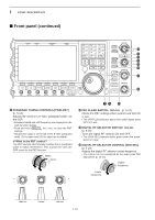
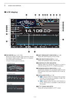
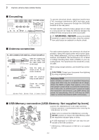
1 PANEL DESCRIPTION i APF/TPF INDICATOR ➥ " APF " appears when the audio peak filter function is in use. This function is available in CW mode. (p. 4-6) ➥ " TPF " appears when the twin peak filter function is in use. This function is available in RTTY mode. (p. 4-14) o CLOCK READOUT Shows the current time. Local and UTC time can be indicated at the same time. !0 USB-MEMORY INDICATOR Appears when USB-Memory is connected and blinks while reading or writing the USB-Memory. !1 RIT INDICATOR Appears when RIT function is in use. !2 ∂TX INDICATOR Appears when ∂TX function is in use. !3 RIT/∂TX SHIFT FREQUENCY INDICATOR Shows the shift frequency for the RIT or ∂TX function. !4 IF FILTER INDICATOR (p. 5-13) Shows the selected IF filter number. !5 QUICK TUNING INDICATOR (p. 3-6) Appears when the quick tuning step function is in use. !6 FREQUENCY READOUTS Shows the operating frequency. !7 MULTI-FUNCTION SCREEN Shows the screens for the multi-function digital meter, spectrum scope, voice recorder, memory list, scan, memory keyer, RTTY decoder, PSK decoder, IF filter selection or set modes, etc. !8 LCD FUNCTION SWITCH GUIDE Indicates the function of the LCD function switches ( F-1 - F-7 ). !9 MEMORY CHANNEL READOUTS ➥ Shows the selected memory channel contents in VFO mode. ➥ Shows the VFO contents in memory mode. @0 MULTI-FUNCTION SWITCH GUIDE Indicates the function of the multi-function switches. @1 SELECT MEMORY CHANNEL INDICATOR (p. 9-7) Indicates the displayed memory channel is set as a select memory channel. @2 SELECT ANTENNA INDICATOR Indicates the selected antenna. @3 TX INDICATOR Indicates the frequency readout for transmit. @4 VFO/MEMORY CHANNEL INDICATOR (p. 3-3) Indicates the VFO mode or selected memory channel number. @5 MODE INDICATOR Shows the selected mode. 1-15
-
 1
1 -
2
-
3
-
4
-
5
-
6
-
7
-
8
-
9
-
10
-
11
-
12
-
13
-
14
-
15
-
16
-
17
-
18
-
19
-
 20
20 -
 21
21 -
 22
22 -
 23
23 -
 24
24 -
 25
25 -
 26
26 -
 27
27 -
 28
28 -
 29
29 -
 30
30 -
31
-
32
-
33
-
34
-
35
-
36
-
37
-
38
-
39
-
40
-
41
-
42
-
43
-
44
-
45
-
46
-
47
-
48
-
49
-
50
-
51
-
52
-
53
-
54
-
55
-
56
-
57
-
58
-
59
-
60
-
61
-
62
-
63
-
64
-
65
-
66
-
67
-
68
-
69
-
70
-
71
-
72
-
73
-
74
-
75
-
76
-
77
-
78
-
79
-
80
-
81
-
82
-
83
-
84
-
85
-
86
-
87
-
88
-
89
-
90
-
91
-
92
-
93
-
94
-
95
-
96
-
97
-
98
-
99
-
100
-
101
-
102
-
103
-
104
-
105
-
106
-
107
-
108
-
109
-
110
-
111
-
112
-
113
-
114
-
115
-
116
-
117
-
118
-
119
-
120
-
121
-
122
-
123
-
124
-
125
-
126
-
127
-
128
-
129
-
130
-
131
-
132
-
133
-
134
-
135
-
136
-
137
-
138
-
139
-
140
-
141
-
142
-
143
-
144
-
145
-
146
-
147
-
148
-
149
-
150
-
151
-
152
-
153
-
154
-
155
-
156
-
157
-
158
-
159
-
160
-
161
-
162
-
163
-
164
-
165
-
166
-
167
-
168
-
169
-
170
-
171
-
172
-
173
-
174
-
175
-
176
-
177
-
178
-
179
-
180
-
181
-
182
-
183
-
184
-
185
-
186
-
187
-
188
-
189
-
190
-
191
-
192
-
193
-
194
-
195
-
196
-
197
-
198
-
199
-
200
-
201
-
202
-
203
-
204
-
205
-
206
-
207
-
208
-
209
-
210
-
211
-
212
-
213
-
214
-
215
-
216
 |
 |