Icom IC-7700 Instruction Manual - Page 91
Fixed mode
 |
View all Icom IC-7700 manuals
Add to My Manuals
Save this manual to your list of manuals |
Page 91 highlights
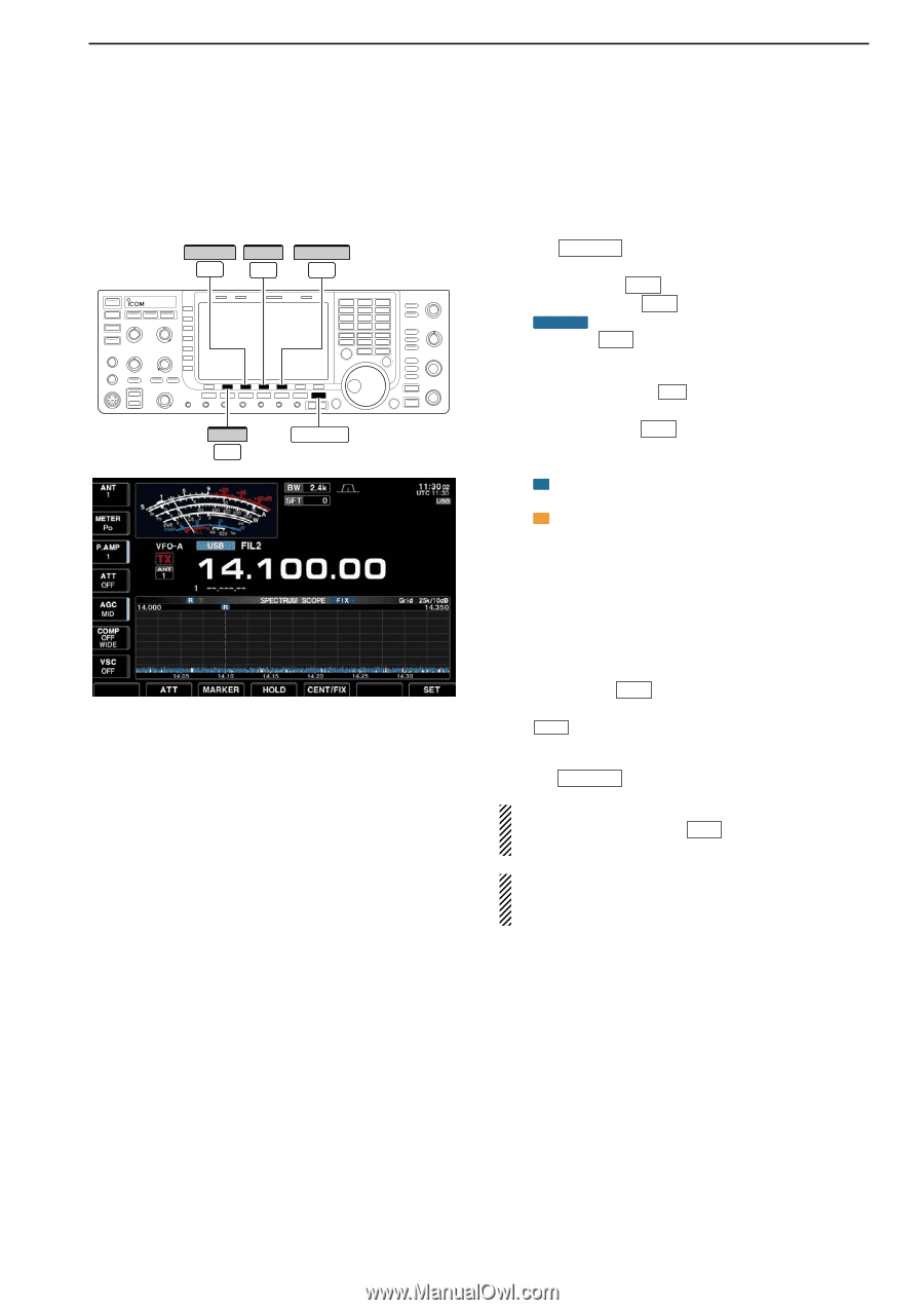
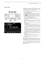
D Fixed mode MARKER HOLD CENT/FIX F-3 F-4 F-5 ATT EXIT/SET F-2 5 FUNCTIONS FOR RECEIVE Displays signals within the specified frequency range. Conditions on the selected frequency band can be observed at a glance when using this mode. q Push EXIT/SET several times to close a multi-function screen, if necessary. w Push [SCOPE] F-1 to select the scope screen. e Push [CENT/FIX] F-5 to select the fixed mode. • " FIX " is displayed when fixed mode is selected. r Push [ATT] F-2 several times to activate an atten- uator or turn the attenuator OFF. • 10, 20 and 30 dB attenuators are available. • Push and hold [ATT] F-2 for 1 sec. to turn OFF the at- tenuator. t Push [MARKER] F-3 several times to select the marker for transmit frequency or turn the marker OFF. • " R " displays the marker at the receive frequency. (al- ways displayed) • " T " displays the marker at the transmit frequency. • "" appears when the marker is out of range. • The spectrum scope shows the transmit signal while transmitting. This can be deactivated in scope set mode. (p. 5-5) • The spectrum scope shows the peak level hold function. Peak levels are displayed in the background of the current spectrum in a different color until the receive frequency changes. This can be deactivated and the waveform color can be set in scope set mode. (p. 5-5) y Push [HOLD] F-4 to freeze the current spectrum waveform. • " HOLD " appears while the function is in use. • The peak hold function can be deactivated in scope set mode. u Push EXIT/SET to exit the scope screen. NOTE: If a strong signal is received, a ghost signal may appear. Push [ATT] F-2 several times to activate the spectrum scope attenuator in this case. The scope bandwidth can be specified for each frequency band independently in scope set mode. (pgs. 5-6 to 5-8) 5-3
-
 1
1 -
2
-
3
-
4
-
5
-
6
-
7
-
8
-
9
-
10
-
11
-
12
-
13
-
14
-
15
-
16
-
17
-
18
-
19
-
20
-
21
-
22
-
23
-
24
-
25
-
26
-
27
-
28
-
29
-
30
-
31
-
32
-
33
-
34
-
35
-
36
-
37
-
38
-
39
-
40
-
41
-
42
-
43
-
44
-
45
-
46
-
47
-
48
-
49
-
50
-
51
-
52
-
53
-
54
-
55
-
56
-
57
-
58
-
59
-
60
-
61
-
62
-
63
-
64
-
65
-
66
-
67
-
68
-
69
-
70
-
71
-
72
-
73
-
74
-
75
-
76
-
77
-
78
-
79
-
80
-
81
-
82
-
83
-
84
-
85
-
 86
86 -
 87
87 -
 88
88 -
 89
89 -
 90
90 -
 91
91 -
 92
92 -
 93
93 -
 94
94 -
 95
95 -
 96
96 -
97
-
98
-
99
-
100
-
101
-
102
-
103
-
104
-
105
-
106
-
107
-
108
-
109
-
110
-
111
-
112
-
113
-
114
-
115
-
116
-
117
-
118
-
119
-
120
-
121
-
122
-
123
-
124
-
125
-
126
-
127
-
128
-
129
-
130
-
131
-
132
-
133
-
134
-
135
-
136
-
137
-
138
-
139
-
140
-
141
-
142
-
143
-
144
-
145
-
146
-
147
-
148
-
149
-
150
-
151
-
152
-
153
-
154
-
155
-
156
-
157
-
158
-
159
-
160
-
161
-
162
-
163
-
164
-
165
-
166
-
167
-
168
-
169
-
170
-
171
-
172
-
173
-
174
-
175
-
176
-
177
-
178
-
179
-
180
-
181
-
182
-
183
-
184
-
185
-
186
-
187
-
188
-
189
-
190
-
191
-
192
-
193
-
194
-
195
-
196
-
197
-
198
-
199
-
200
-
201
-
202
-
203
-
204
-
205
-
206
-
207
-
208
-
209
-
210
-
211
-
212
-
213
-
214
-
215
-
216
 |
 |