Icom IC-7700 Instruction Manual - Page 16
Multi-function Switches, Mf1 Multi-function 1 Switch, Mf2 Multi-function 2 Switch, Mf3 Multi-
 |
View all Icom IC-7700 manuals
Add to My Manuals
Save this manual to your list of manuals |
Page 16 highlights
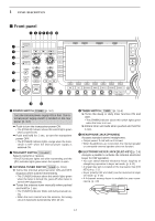
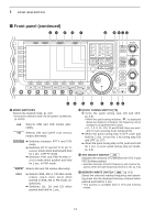
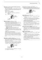
1 PANEL DESCRIPTION ■ Front panel (continued) #3 #4 #5 #6 #7 #8 #9 $0 $1 $2 NSCEIVER 7700 MONITOR D DELAY NB NB RF DRIVE TX RX SPLIT LOCK 1.8 1 10 4 21 7 GENE 3.5 2 14 5 24 8 50 0 MP-W MW 7 3 18 6 28 9 F-INP ENT MP-R V/M XFC A/B A=B TS F-1 F-2 SSB CW COMP MONI GAIN F-3 RTTY/PSK F-4 AM/FM F-5 DATA VOX GAIN ANTI VOX CONTRAST F-6 M.SCOPE F-7 EXIT/SET BRIGHT REC PLAY VOICE MEMORY AUTO TUNE LOCK FILTER PBT-CLR TWIN-PBT DIGI-SEL DIGI-SEL NOTCH APF/TPF NOTCH RIT/∂TX RIT ∂TX CLEAR SPEECH CW PITCH SPLIT #3 MULTI-FUNCTION SWITCHES Push to select the functions indicated in the LCD display to the right of these switches. • Functions vary depending on the operating condition. MF1 (MULTI-FUNCTION 1 SWITCH) ANT ➥ Selects the antenna connector from 1 ANT1, ANT2, ANT3 and ANT4 when pushed. (p. 10-2) ➥ Displays antenna selection memory when pushed and held for 1 sec. • When the receive antenna is activated, the antenna connected to [ANT4] is used for receive only. When a transverter is in use, this [ANT] does not function and 'TRV' appears. MF2 (MULTI-FUNCTION 2 SWITCH) METER ➥ Selects RF power (Po), SWR, ALC, Po COMP, VD or ID metering during trans- mit. (p. 3-10) ➥ Switches the multi-function digital meter ON and OFF when pushed and held for 1 sec. (p. 3-10) MF3 (MULTI-FUNCTION 3 SWITCH) P.AMP ➥ Selects one of 2 receive RF preamps 1 or bypasses them. (p. 5-9) • "P. AMP1" activates 10 dB preamp. • "P. AMP2" activates 16 dB high-gain pre- amp. ➥ Turns the preamp function OFF when pushed and held for 1 sec. (p. 5-9) ✔ What is the preamp? The preamp amplifies signals in the receiver front end to improve S/N ratio and sensitivity. Select "P. AMP1" or "P. AMP2" when receiving weak signals. MF4 (MULTI-FUNCTION 4 SWITCH) ➥ Selects 6 dB, 12 dB or 18 dB attenua- ATT OFF tor when pushed. (p. 5-9) ➥ Turns the attenuator function OFF when pushed and held for 1 sec. (p. 5-9) ✔ What is the attenuator? The attenuator prevents a desired signal from being distorted when very strong signals are near the desired frequency, or when very strong electromagnetic fields, such as from a broadcasting station, are near your location. 1-6
-
 1
1 -
2
-
3
-
4
-
5
-
6
-
7
-
8
-
9
-
10
-
 11
11 -
 12
12 -
 13
13 -
 14
14 -
 15
15 -
 16
16 -
 17
17 -
 18
18 -
 19
19 -
 20
20 -
 21
21 -
22
-
23
-
24
-
25
-
26
-
27
-
28
-
29
-
30
-
31
-
32
-
33
-
34
-
35
-
36
-
37
-
38
-
39
-
40
-
41
-
42
-
43
-
44
-
45
-
46
-
47
-
48
-
49
-
50
-
51
-
52
-
53
-
54
-
55
-
56
-
57
-
58
-
59
-
60
-
61
-
62
-
63
-
64
-
65
-
66
-
67
-
68
-
69
-
70
-
71
-
72
-
73
-
74
-
75
-
76
-
77
-
78
-
79
-
80
-
81
-
82
-
83
-
84
-
85
-
86
-
87
-
88
-
89
-
90
-
91
-
92
-
93
-
94
-
95
-
96
-
97
-
98
-
99
-
100
-
101
-
102
-
103
-
104
-
105
-
106
-
107
-
108
-
109
-
110
-
111
-
112
-
113
-
114
-
115
-
116
-
117
-
118
-
119
-
120
-
121
-
122
-
123
-
124
-
125
-
126
-
127
-
128
-
129
-
130
-
131
-
132
-
133
-
134
-
135
-
136
-
137
-
138
-
139
-
140
-
141
-
142
-
143
-
144
-
145
-
146
-
147
-
148
-
149
-
150
-
151
-
152
-
153
-
154
-
155
-
156
-
157
-
158
-
159
-
160
-
161
-
162
-
163
-
164
-
165
-
166
-
167
-
168
-
169
-
170
-
171
-
172
-
173
-
174
-
175
-
176
-
177
-
178
-
179
-
180
-
181
-
182
-
183
-
184
-
185
-
186
-
187
-
188
-
189
-
190
-
191
-
192
-
193
-
194
-
195
-
196
-
197
-
198
-
199
-
200
-
201
-
202
-
203
-
204
-
205
-
206
-
207
-
208
-
209
-
210
-
211
-
212
-
213
-
214
-
215
-
216
 |
 |