Icom IC-7700 Instruction Manual - Page 28
Unpacking, Main dial attachment
 |
View all Icom IC-7700 manuals
Add to My Manuals
Save this manual to your list of manuals |
Page 28 highlights
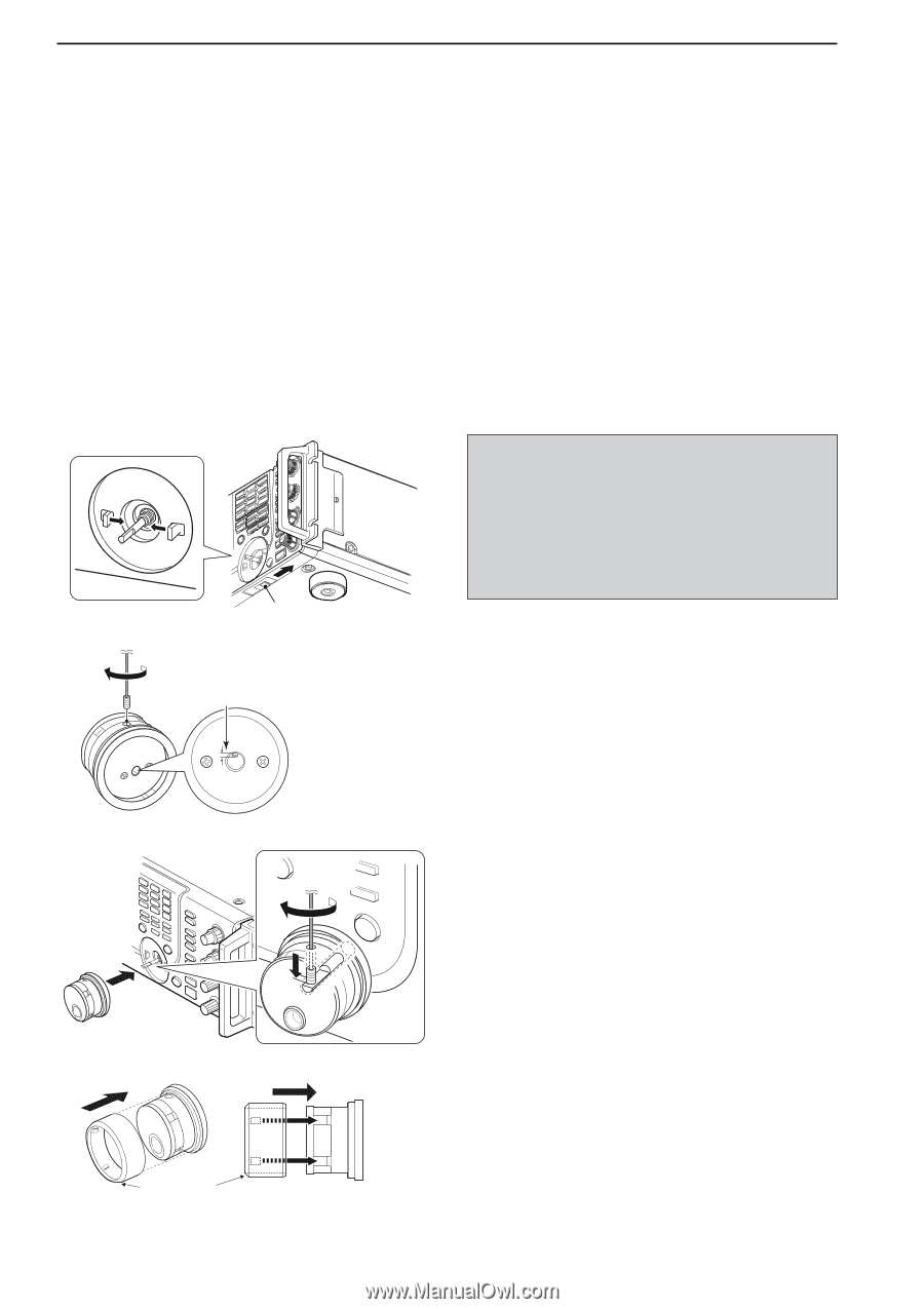
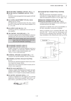
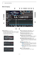
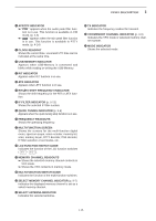
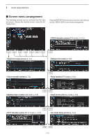
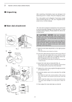
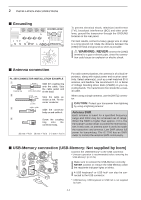
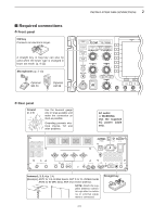
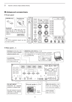
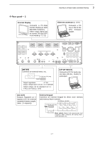
2 INSTALLATION AND CONNECTIONS ■ Unpacking ■ Main dial attachment q Dial brake adjustment Fig. 1 w Shorter than 1 mm (1/32 in) Fig. 2 e r Fig. 3 t After unpacking, immediately report any damage to the delivering carrier or dealer. Keep the shipping cartons. For a description and a diagram of accessory equipment included with the IC-7700, see 'Supplied accessories' on p. iii of this manual. The main dial is shipped unattached to the transceiver to prevent possible damage to the dial shaft or rotary encoder during shipping. Please attach the dial as described below. R CAUTION!: NEVER hold any controller knob(s), such as the main dial, when carrying or lifting the transceiver. This will damage the dial shaft or rotary encoder. Once attaching the rubber cover to the main dial, it's hard to remove. When you remove the rubber cover from main dial, be careful to lack your nails and/or damage to the transceiver. q Slide the dial brake adjustment to the right position (Fig. 1). • The dial brakes move inward as shown. w Insert the main dial set-screw into the screw hole of the main dial, then tighten the screw until the screw extends into the shaft hole out slightly using supplied hexagonal wrench (2 mm) (Fig. 2). • Be careful that the screw does not extend out more than 1 mm (1/32 in). e Attach the main dial as illustrated (Fig. 3). • Be careful to match the correct orientation of the flat face of the shaft and the screw hole of the dial knob. r Tighten the screw using supplied hexagonal wrench as illustrated (Fig. 3). t Install the rubber cover to the main dial (Fig. 4) little by little. • Be careful to match the correct position of the convex part of the rubber cover and the concave part of the dial knob. • Never install the rubber cover on the main dial by force. This may cause damage to the dial shaft or rotary encoder. y Then adjust the main dial brake as desired. Front side Side view Fig. 4 2-2
-
 1
1 -
2
-
3
-
4
-
5
-
6
-
7
-
8
-
9
-
10
-
11
-
12
-
13
-
14
-
15
-
16
-
17
-
18
-
19
-
20
-
21
-
22
-
 23
23 -
 24
24 -
 25
25 -
 26
26 -
 27
27 -
 28
28 -
 29
29 -
 30
30 -
 31
31 -
 32
32 -
 33
33 -
34
-
35
-
36
-
37
-
38
-
39
-
40
-
41
-
42
-
43
-
44
-
45
-
46
-
47
-
48
-
49
-
50
-
51
-
52
-
53
-
54
-
55
-
56
-
57
-
58
-
59
-
60
-
61
-
62
-
63
-
64
-
65
-
66
-
67
-
68
-
69
-
70
-
71
-
72
-
73
-
74
-
75
-
76
-
77
-
78
-
79
-
80
-
81
-
82
-
83
-
84
-
85
-
86
-
87
-
88
-
89
-
90
-
91
-
92
-
93
-
94
-
95
-
96
-
97
-
98
-
99
-
100
-
101
-
102
-
103
-
104
-
105
-
106
-
107
-
108
-
109
-
110
-
111
-
112
-
113
-
114
-
115
-
116
-
117
-
118
-
119
-
120
-
121
-
122
-
123
-
124
-
125
-
126
-
127
-
128
-
129
-
130
-
131
-
132
-
133
-
134
-
135
-
136
-
137
-
138
-
139
-
140
-
141
-
142
-
143
-
144
-
145
-
146
-
147
-
148
-
149
-
150
-
151
-
152
-
153
-
154
-
155
-
156
-
157
-
158
-
159
-
160
-
161
-
162
-
163
-
164
-
165
-
166
-
167
-
168
-
169
-
170
-
171
-
172
-
173
-
174
-
175
-
176
-
177
-
178
-
179
-
180
-
181
-
182
-
183
-
184
-
185
-
186
-
187
-
188
-
189
-
190
-
191
-
192
-
193
-
194
-
195
-
196
-
197
-
198
-
199
-
200
-
201
-
202
-
203
-
204
-
205
-
206
-
207
-
208
-
209
-
210
-
211
-
212
-
213
-
214
-
215
-
216
 |
 |