Icom IC-7700 Instruction Manual - Page 24
LCD display
 |
View all Icom IC-7700 manuals
Add to My Manuals
Save this manual to your list of manuals |
Page 24 highlights
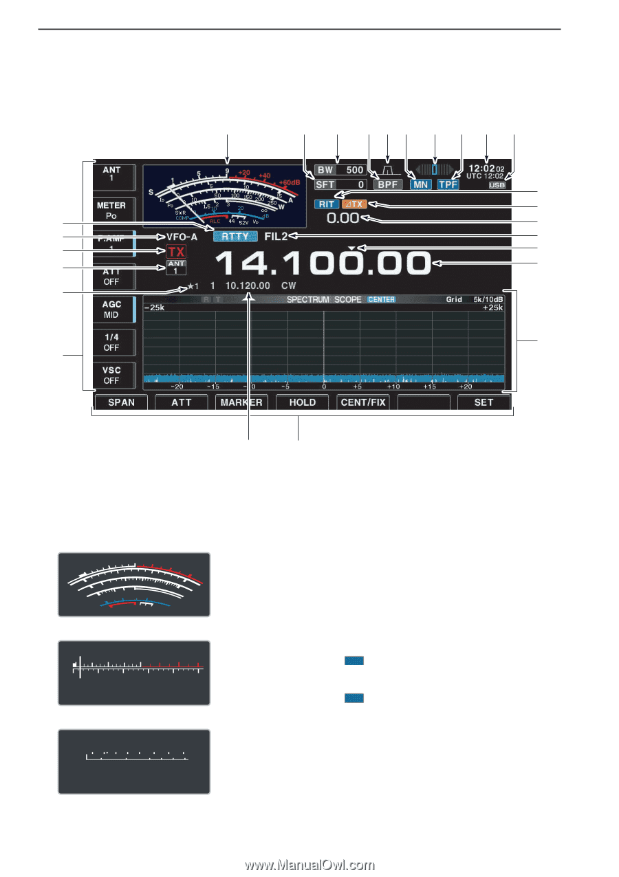
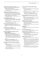
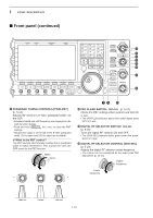
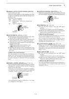
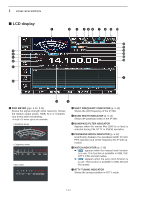
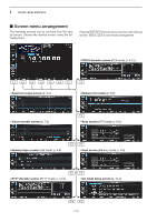
1 PANEL DESCRIPTION ■ LCD display q @5 @4 @3 @2 @1 @0 w e r t y u i o !0 !1 !2 !3 !4 !5 !6 !7 !9 !8 q S/RF METER (pgs. 3-10, 3-11) Shows the signal strength while receiving. Shows the relative output power, SWR, ALC or compression levels while transmitting. • A total of 3 meter types are available. • Standard meter 5 9 +20 +40 1 +60dB 5 10 S 0 ID Po 0 10 SWR 10 COMP 50 1.5102 ALC ∞ 100 150 3 20 200 15 250 W A dB 44 52V VD • Edgewise meter S1 Po 0 3 5 7 9 +20 +40 +60dB 50 100 150 200 250W • Bar meter S 1 3 5 7 9 +20 +40 +60dB Po 0 10 50 100 150 200 250W w SHIFT FREQUENCY INDICATOR (p. 5-12) Shows the shift frequency of the IF filter. e BAND WIDTH INDICATOR (p. 5-12) Shows the passband width of the IF filter. r BANDPASS FILTER INDICATOR Appears when the narrow filter (500 Hz or less) is selected during CW, RTTY or PSK31 operation. t PASSBAND WIDTH INDICATOR (p. 5-12) Graphically displays the passband width for twin PBT operation and center frequency for IF shift operation. y NOTCH INDICATOR (p. 5-18) ➥ " MN " appears when the manual notch function is in use. This function is available in SSB, CW, RTTY, PSK and AM modes. ➥ " AN " appears when the auto notch function is in use. This function is available in SSB, AM and FM modes. u RTTY TUNING INDICATOR Shows the tuning condition in RTTY mode. 1-14
-
 1
1 -
2
-
3
-
4
-
5
-
6
-
7
-
8
-
9
-
10
-
11
-
12
-
13
-
14
-
15
-
16
-
17
-
18
-
 19
19 -
 20
20 -
 21
21 -
 22
22 -
 23
23 -
 24
24 -
 25
25 -
 26
26 -
 27
27 -
 28
28 -
 29
29 -
30
-
31
-
32
-
33
-
34
-
35
-
36
-
37
-
38
-
39
-
40
-
41
-
42
-
43
-
44
-
45
-
46
-
47
-
48
-
49
-
50
-
51
-
52
-
53
-
54
-
55
-
56
-
57
-
58
-
59
-
60
-
61
-
62
-
63
-
64
-
65
-
66
-
67
-
68
-
69
-
70
-
71
-
72
-
73
-
74
-
75
-
76
-
77
-
78
-
79
-
80
-
81
-
82
-
83
-
84
-
85
-
86
-
87
-
88
-
89
-
90
-
91
-
92
-
93
-
94
-
95
-
96
-
97
-
98
-
99
-
100
-
101
-
102
-
103
-
104
-
105
-
106
-
107
-
108
-
109
-
110
-
111
-
112
-
113
-
114
-
115
-
116
-
117
-
118
-
119
-
120
-
121
-
122
-
123
-
124
-
125
-
126
-
127
-
128
-
129
-
130
-
131
-
132
-
133
-
134
-
135
-
136
-
137
-
138
-
139
-
140
-
141
-
142
-
143
-
144
-
145
-
146
-
147
-
148
-
149
-
150
-
151
-
152
-
153
-
154
-
155
-
156
-
157
-
158
-
159
-
160
-
161
-
162
-
163
-
164
-
165
-
166
-
167
-
168
-
169
-
170
-
171
-
172
-
173
-
174
-
175
-
176
-
177
-
178
-
179
-
180
-
181
-
182
-
183
-
184
-
185
-
186
-
187
-
188
-
189
-
190
-
191
-
192
-
193
-
194
-
195
-
196
-
197
-
198
-
199
-
200
-
201
-
202
-
203
-
204
-
205
-
206
-
207
-
208
-
209
-
210
-
211
-
212
-
213
-
214
-
215
-
216
 |
 |