Icom IC-7700 Instruction Manual - Page 13
Panel Description - cw keyer
 |
View all Icom IC-7700 manuals
Add to My Manuals
Save this manual to your list of manuals |
Page 13 highlights
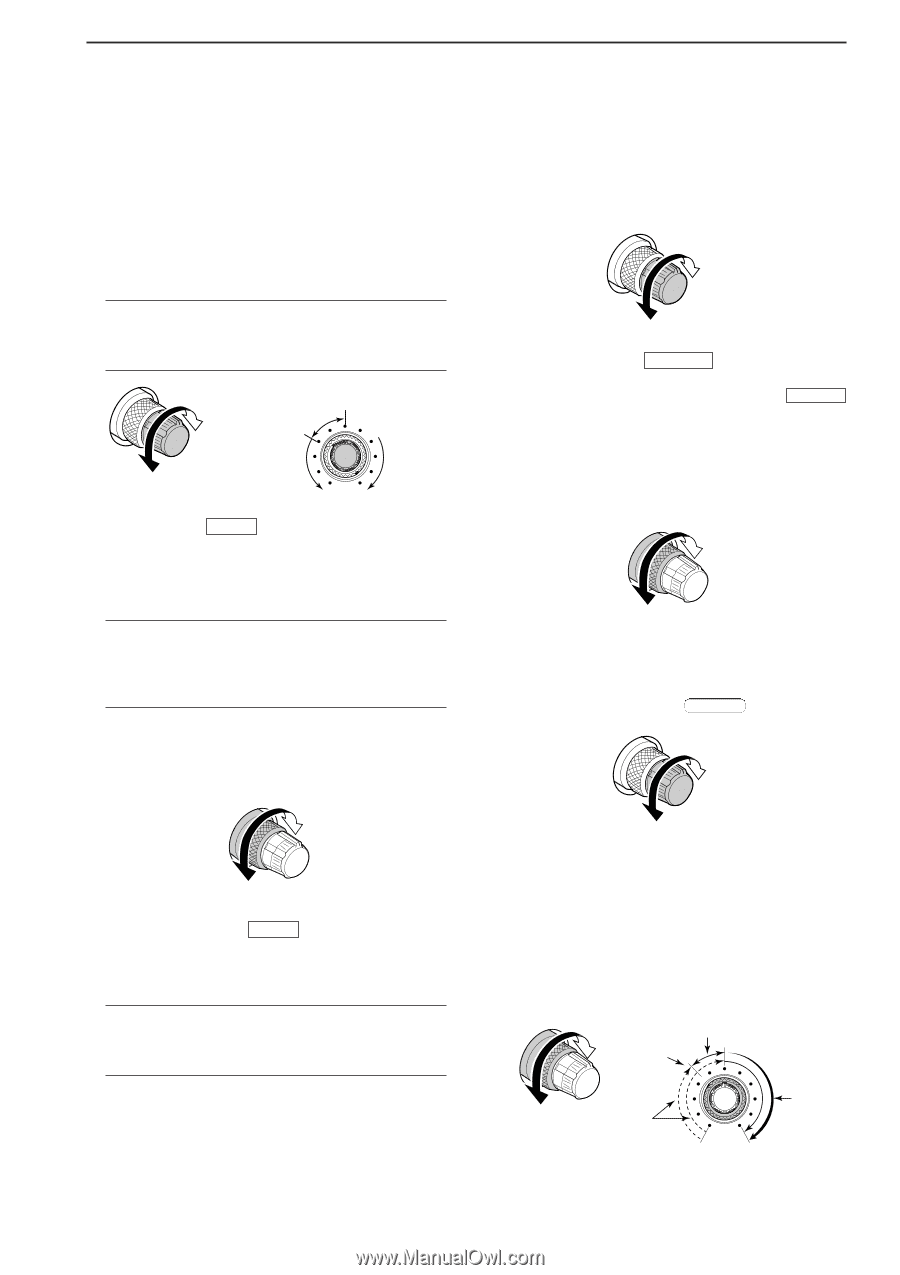
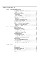
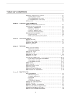
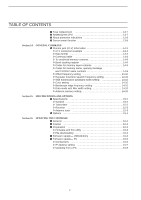
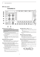
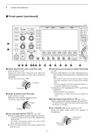
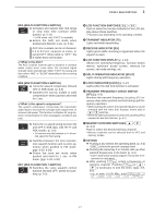
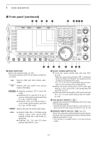
1 PANEL DESCRIPTION u MICROPHONE CONNECTOR [MIC] Accepts an optional microphone. • See p. 15-4 for appropriate microphones. • See p. 2-10 for microphone connector information. i MIC GAIN CONTROL [MIC] (p. 3-12) Adjusts microphone input gain. • The transmit audio tone in SSB, AM and FM modes can be adjusted independently in set mode. (p. 12-5) ✔ How to set the microphone gain. Set the [MIC] control so that the ALC meter occasionally moves up-scale during normal voice transmission in SSB, AM or FM mode. Recommended level for an Icom microphone Increases Decreases Decreases Increases o VOX SWITCH VOX ➥ Push to turn the VOX function ON and OFF during SSB, AM and FM mode operation. (p. 6-2) ➥ Push and hold for 1 sec. to enter VOX set mode. (p. 6-2) ✔ What is the VOX function? The VOX function (voice operated transmission) activates transmission without pushing the transmit switch or PTT switch when you speak into the microphone; then automatically returns to receive when you stop speaking. !0 RF POWER CONTROL [RF PWR] (p. 3-12) Continuously varies the RF output power from minimum (5 W*) to maximum (200 W*). *AM mode: 5 W to 50 W Increases Decreases !1 BREAK-IN SWITCH BK-IN Push to turn the break-in function ON (semi-break-in, full-break-in) and OFF during CW mode operation. (p. 6-3) ✔ What is the break-in function? The break-in function switches transmit and receive with CW keying. Full break-in (QSK) can monitor the receive signal between CW dots and dashes. !2 ELECTRONIC CW KEYER SPEED CONTROL [KEY SPEED] (p. 4-4) Adjusts keying speed for the internal electronic CW keyer. • 6 wpm (min.) to 48 wpm (max.) is the available range. Max. 48 wpm Min. 6 wpm !3 MONITOR SWITCH MONITOR (p. 6-4) Monitors your transmitted IF signal. • The CW sidetone functions regardless of MONITOR switch setting in CW mode. • The [MONITOR] indicator above this switch lights green while the function is activated. !4 BREAK-IN DELAY CONTROL [DELAY] (p. 6-3) Adjusts the transmit-to-receive switching delay time for CW semi-break-in operations. Long delay for slow speed keying Short delay for high speed keying !5 AGC CONTROL [AGC] (p. 5-11) Adjusts the continuously-variable AGC circuit time constant. • To use [AGC] control, push AGC VR ([AGC VR] indicator lights). Slow Fast !6 SQUELCH CONTROL [SQL] (outer control; p. 3-9) Adjusts the squelch threshold level. The squelch mutes noise output from the speaker (closed condition) when no signal is received. • The squelch is particularly effective for FM. It is also available in other modes. • The 11 to 12 o'clock position is recommended for the most effective use of the [SQL] control. Deep Squelch threshold Noise squelch Shallow Squelch is open Shallow S-meter squelch Deep 1-3
-
 1
1 -
2
-
3
-
4
-
5
-
6
-
7
-
 8
8 -
 9
9 -
 10
10 -
 11
11 -
 12
12 -
 13
13 -
 14
14 -
 15
15 -
 16
16 -
 17
17 -
 18
18 -
19
-
20
-
21
-
22
-
23
-
24
-
25
-
26
-
27
-
28
-
29
-
30
-
31
-
32
-
33
-
34
-
35
-
36
-
37
-
38
-
39
-
40
-
41
-
42
-
43
-
44
-
45
-
46
-
47
-
48
-
49
-
50
-
51
-
52
-
53
-
54
-
55
-
56
-
57
-
58
-
59
-
60
-
61
-
62
-
63
-
64
-
65
-
66
-
67
-
68
-
69
-
70
-
71
-
72
-
73
-
74
-
75
-
76
-
77
-
78
-
79
-
80
-
81
-
82
-
83
-
84
-
85
-
86
-
87
-
88
-
89
-
90
-
91
-
92
-
93
-
94
-
95
-
96
-
97
-
98
-
99
-
100
-
101
-
102
-
103
-
104
-
105
-
106
-
107
-
108
-
109
-
110
-
111
-
112
-
113
-
114
-
115
-
116
-
117
-
118
-
119
-
120
-
121
-
122
-
123
-
124
-
125
-
126
-
127
-
128
-
129
-
130
-
131
-
132
-
133
-
134
-
135
-
136
-
137
-
138
-
139
-
140
-
141
-
142
-
143
-
144
-
145
-
146
-
147
-
148
-
149
-
150
-
151
-
152
-
153
-
154
-
155
-
156
-
157
-
158
-
159
-
160
-
161
-
162
-
163
-
164
-
165
-
166
-
167
-
168
-
169
-
170
-
171
-
172
-
173
-
174
-
175
-
176
-
177
-
178
-
179
-
180
-
181
-
182
-
183
-
184
-
185
-
186
-
187
-
188
-
189
-
190
-
191
-
192
-
193
-
194
-
195
-
196
-
197
-
198
-
199
-
200
-
201
-
202
-
203
-
204
-
205
-
206
-
207
-
208
-
209
-
210
-
211
-
212
-
213
-
214
-
215
-
216
 |
 |