Icom IC-7700 Instruction Manual - Page 37
Accessory connector information - mods
 |
View all Icom IC-7700 manuals
Add to My Manuals
Save this manual to your list of manuals |
Page 37 highlights
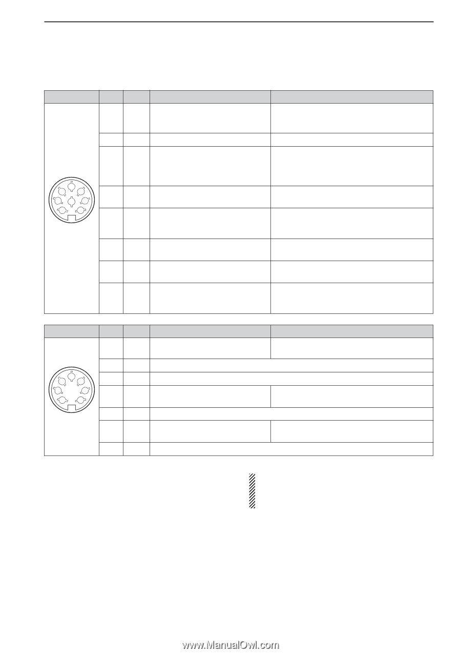
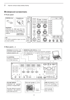
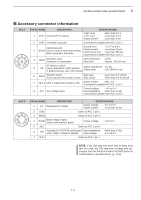
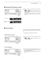
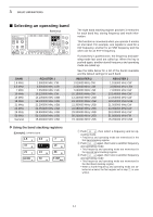
2 INSTALLATION AND CONNECTIONS ■ Accessory connector information ACC 1 2 45 183 67 PIN No. NAME DESCRIPTION 1 RTTY Controls RTTY keying SPECIFICATIONS "High" level "Low" level Output current : More than 2.4 V : Less than 0.6 V : Less than 2 mA 2 GND Connects to ground. Connected in parallel with ACC 2 pin 2. 3 Input/output pin. SEND Goes to ground when transmitting. When grounded, transmits. Ground level : -0.5 V to 0.8 V Output current : Less than 20 mA Input current (Tx) : Less than 200 mA Connected in parallel with ACC 2 pin 3. 4 MOD Modulator input. Connects to a modulator. Input impedance : 10 kΩ Input level : Approx. 100 mV rms 5 AF AF detector output. Fixed, regardless of [AF] position in default settings. (see notes below) Output Output impedance level : 4.7 kΩ : 100-300 mV rms 6 SQLS Squelch output. Goes to ground when squelch opens. SQL open SQL closed : Less than 0.3 V/5 mA : More than 6.0 V/100 µA 7 13.8 V 13.8 V output when power is ON. Output current : Max. 1 A Connected in parallel with ACC 2 pin 7. 8 ALC ALC voltage input. Control voltage : -4 V to 0 V Input impedance : More than 10 kΩ Connected in parallel with ACC 2 pin 5. ACC 2 2 45 1 3 67 PIN No. NAME DESCRIPTION 1 8 V Regulated 8 V output. SPECIFICATIONS Output voltage Output current : 8 V ±0.3 V : Less than 10 mA 2 GND Same as ACC 1 pin 2. 3 SEND Same as ACC 1 pin 3. 4 BAND Band voltage output. (Varies with amateur band) Output voltage : 0 to 8.0 V 5 ALC Same as ACC 1 pin 8. 6 TRV Activates [X-VERTER] input/output Input impedance when "HIGH" voltage is applied. Input voltage : More than 10 kΩ : 2 to 13.8 V 7 13.8 V Same as ACC 1 pin 7. NOTE: If the CW side tone level limit or beep level limit is in use, the CW side tone or beep tone decreases from the fixed level when the [AF] control is rotated above a specified level. (p. 12-6) 2-11
-
 1
1 -
2
-
3
-
4
-
5
-
6
-
7
-
8
-
9
-
10
-
11
-
12
-
13
-
14
-
15
-
16
-
17
-
18
-
19
-
20
-
21
-
22
-
23
-
24
-
25
-
26
-
27
-
28
-
29
-
30
-
31
-
 32
32 -
 33
33 -
 34
34 -
 35
35 -
 36
36 -
 37
37 -
 38
38 -
 39
39 -
 40
40 -
 41
41 -
 42
42 -
43
-
44
-
45
-
46
-
47
-
48
-
49
-
50
-
51
-
52
-
53
-
54
-
55
-
56
-
57
-
58
-
59
-
60
-
61
-
62
-
63
-
64
-
65
-
66
-
67
-
68
-
69
-
70
-
71
-
72
-
73
-
74
-
75
-
76
-
77
-
78
-
79
-
80
-
81
-
82
-
83
-
84
-
85
-
86
-
87
-
88
-
89
-
90
-
91
-
92
-
93
-
94
-
95
-
96
-
97
-
98
-
99
-
100
-
101
-
102
-
103
-
104
-
105
-
106
-
107
-
108
-
109
-
110
-
111
-
112
-
113
-
114
-
115
-
116
-
117
-
118
-
119
-
120
-
121
-
122
-
123
-
124
-
125
-
126
-
127
-
128
-
129
-
130
-
131
-
132
-
133
-
134
-
135
-
136
-
137
-
138
-
139
-
140
-
141
-
142
-
143
-
144
-
145
-
146
-
147
-
148
-
149
-
150
-
151
-
152
-
153
-
154
-
155
-
156
-
157
-
158
-
159
-
160
-
161
-
162
-
163
-
164
-
165
-
166
-
167
-
168
-
169
-
170
-
171
-
172
-
173
-
174
-
175
-
176
-
177
-
178
-
179
-
180
-
181
-
182
-
183
-
184
-
185
-
186
-
187
-
188
-
189
-
190
-
191
-
192
-
193
-
194
-
195
-
196
-
197
-
198
-
199
-
200
-
201
-
202
-
203
-
204
-
205
-
206
-
207
-
208
-
209
-
210
-
211
-
212
-
213
-
214
-
215
-
216
 |
 |