Icom IC-7700 Instruction Manual - Page 42
Selecting an operating band
 |
View all Icom IC-7700 manuals
Add to My Manuals
Save this manual to your list of manuals |
Page 42 highlights
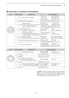
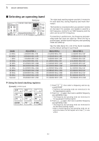
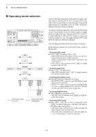
3 BASIC OPERATIONS ■ Selecting an operating band Band keys The triple band stacking register provides 3 memories for each band key, storing frequency and mode information. This function is convenient when you operate 3 modes on one band. For example, one register is used for a CW frequency, another for an SSB frequency and the other one for an RTTY frequency. If a band key is pushed once, the frequency and operating mode last used are called up. When the key is pushed again, another stored frequency and operating mode are called up. See the table below for a list of the bands available and the default settings for each band. BAND 1.8 MHz 3.5 MHz 7 MHz 10 MHz 14 MHz 18 MHz 21 MHz 24 MHz 28 MHz 50 MHz General REGISTER 1 1.900000 MHz CW 3.550000 MHz LSB 7.050000 MHz LSB 10.120000 MHz CW 14.100000 MHz USB 18.100000 MHz USB 21.200000 MHz USB 24.950000 MHz USB 28.500000 MHz USB 50.100000 MHz USB 15.000000 MHz USB REGISTER 2 1.910000 MHz CW 3.560000 MHz LSB 7.060000 MHz LSB 10.130000 MHz CW 14.200000 MHz USB 18.130000 MHz USB 21.300000 MHz USB 24.980000 MHz USB 29.500000 MHz USB 50.200000 MHz USB 15.100000 MHz USB REGISTER 3 1.915000 MHz CW 3.580000 MHz LSB 7.020000 MHz CW 10.140000 MHz CW 14.050000 MHz CW 18.150000 MHz USB 21.050000 MHz CW 24.900000 MHz CW 28.100000 MHz CW 51.000000 MHz FM 15.200000 MHz USB D Using the band stacking registers [Example]: 14 MHz band 1.8 1 10 4 21 7 GENE 3.5 2 14 5 24 8 50 0 73 18 6 28 9 F-INP ENT q Push 14 5 , then select a frequency and an operating mode. • Frequency and operating mode are memorized in the first band stacking register. w Push 14 5 again, then tune to another frequency and operating mode. • This frequency and operating mode are memorized in the second band stacking register. e Push 14 5 again, then tune to another frequency and operating mode. • This frequency and operating mode are memorized in the third band stacking register. • When a fourth frequency and operating mode are selected on a band, the first register set in step q, is over written. 3-4
-
 1
1 -
2
-
3
-
4
-
5
-
6
-
7
-
8
-
9
-
10
-
11
-
12
-
13
-
14
-
15
-
16
-
17
-
18
-
19
-
20
-
21
-
22
-
23
-
24
-
25
-
26
-
27
-
28
-
29
-
30
-
31
-
32
-
33
-
34
-
35
-
36
-
 37
37 -
 38
38 -
 39
39 -
 40
40 -
 41
41 -
 42
42 -
 43
43 -
 44
44 -
 45
45 -
 46
46 -
 47
47 -
48
-
49
-
50
-
51
-
52
-
53
-
54
-
55
-
56
-
57
-
58
-
59
-
60
-
61
-
62
-
63
-
64
-
65
-
66
-
67
-
68
-
69
-
70
-
71
-
72
-
73
-
74
-
75
-
76
-
77
-
78
-
79
-
80
-
81
-
82
-
83
-
84
-
85
-
86
-
87
-
88
-
89
-
90
-
91
-
92
-
93
-
94
-
95
-
96
-
97
-
98
-
99
-
100
-
101
-
102
-
103
-
104
-
105
-
106
-
107
-
108
-
109
-
110
-
111
-
112
-
113
-
114
-
115
-
116
-
117
-
118
-
119
-
120
-
121
-
122
-
123
-
124
-
125
-
126
-
127
-
128
-
129
-
130
-
131
-
132
-
133
-
134
-
135
-
136
-
137
-
138
-
139
-
140
-
141
-
142
-
143
-
144
-
145
-
146
-
147
-
148
-
149
-
150
-
151
-
152
-
153
-
154
-
155
-
156
-
157
-
158
-
159
-
160
-
161
-
162
-
163
-
164
-
165
-
166
-
167
-
168
-
169
-
170
-
171
-
172
-
173
-
174
-
175
-
176
-
177
-
178
-
179
-
180
-
181
-
182
-
183
-
184
-
185
-
186
-
187
-
188
-
189
-
190
-
191
-
192
-
193
-
194
-
195
-
196
-
197
-
198
-
199
-
200
-
201
-
202
-
203
-
204
-
205
-
206
-
207
-
208
-
209
-
210
-
211
-
212
-
213
-
214
-
215
-
216
 |
 |
