Icom IC-7700 Instruction Manual - Page 147
Receive antenna I/O setting
 |
View all Icom IC-7700 manuals
Add to My Manuals
Save this manual to your list of manuals |
Page 147 highlights
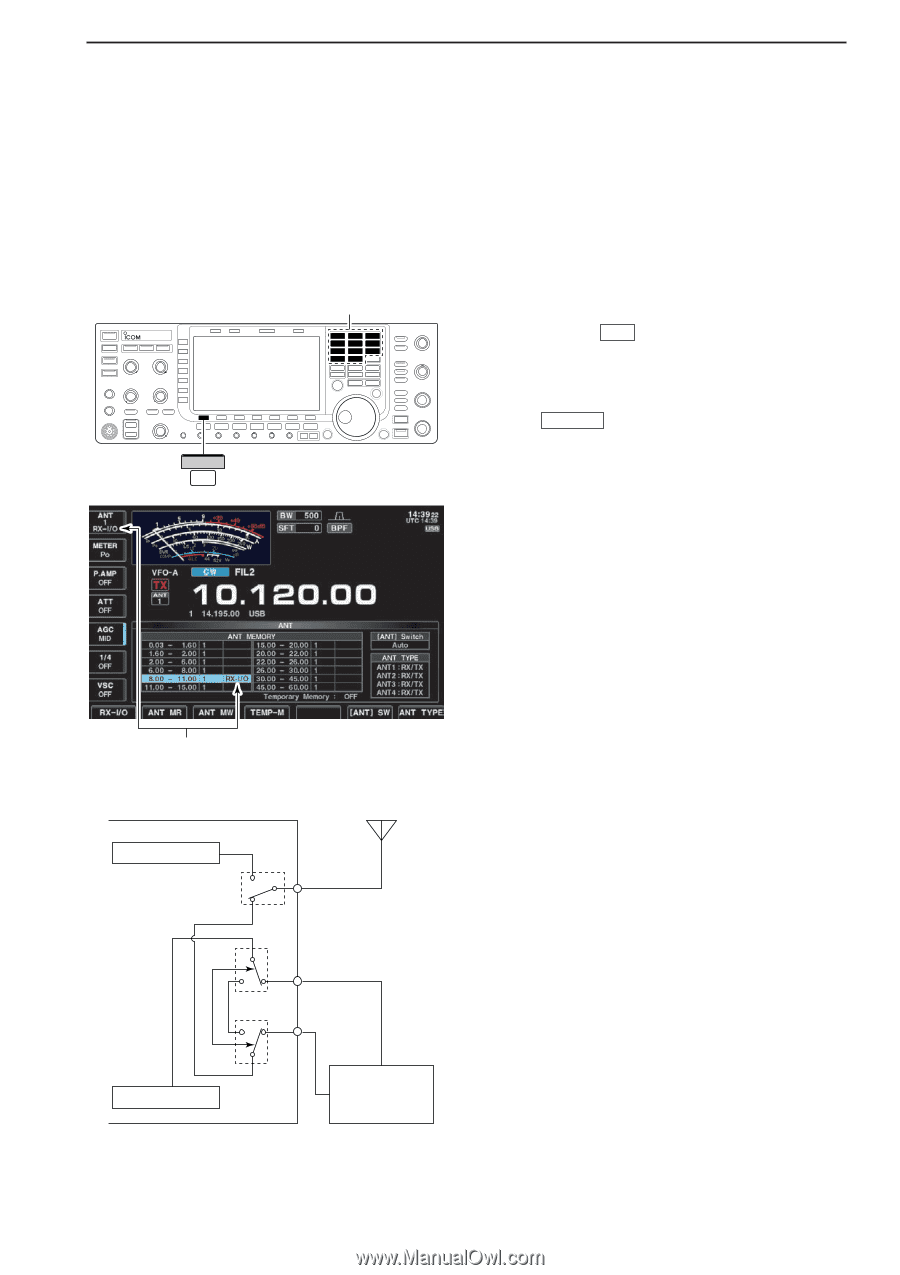
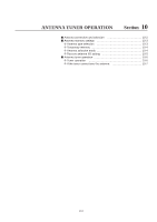
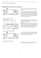
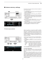
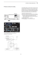
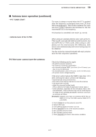
D Receive antenna I/O setting Band keys RX-I/O F-1 10 ANTENNA TUNER OPERATION In the default setting, receive antenna connectors, [RX ANT-IN] and [RX ANT-OUT], on the rear panel are deactivated and are connected internally by the switching relay. If you want to connect an external preamp or low-pass filter between the [RX ANT-IN] and [RX ANTOUT], you must activate them as described below. q Select the antenna set screen. w Select the desired frequency band with a band key. e Push [RX-I/O] F-1 to activate the receive antenna connectors ([RX ANT-IN] and [RX ANT-OUT]). • "RX-I/O" indicators appear when [RX ANT-IN] and [RX- ANT-OUT] are active. r Repeat steps w and e, if desired. t Push EXIT/SET to exit antenna set screen. "RX-I/O" indicators appear when [RX ANT-IN] and [RX ANT-OUT] are active. Transceiver Transmitter Transmit/Receive ANT switching circuit Receiver IN [RX ANT] OUT Preamp or Low-pass filter, etc. 10-5
-
 1
1 -
2
-
3
-
4
-
5
-
6
-
7
-
8
-
9
-
10
-
11
-
12
-
13
-
14
-
15
-
16
-
17
-
18
-
19
-
20
-
21
-
22
-
23
-
24
-
25
-
26
-
27
-
28
-
29
-
30
-
31
-
32
-
33
-
34
-
35
-
36
-
37
-
38
-
39
-
40
-
41
-
42
-
43
-
44
-
45
-
46
-
47
-
48
-
49
-
50
-
51
-
52
-
53
-
54
-
55
-
56
-
57
-
58
-
59
-
60
-
61
-
62
-
63
-
64
-
65
-
66
-
67
-
68
-
69
-
70
-
71
-
72
-
73
-
74
-
75
-
76
-
77
-
78
-
79
-
80
-
81
-
82
-
83
-
84
-
85
-
86
-
87
-
88
-
89
-
90
-
91
-
92
-
93
-
94
-
95
-
96
-
97
-
98
-
99
-
100
-
101
-
102
-
103
-
104
-
105
-
106
-
107
-
108
-
109
-
110
-
111
-
112
-
113
-
114
-
115
-
116
-
117
-
118
-
119
-
120
-
121
-
122
-
123
-
124
-
125
-
126
-
127
-
128
-
129
-
130
-
131
-
132
-
133
-
134
-
135
-
136
-
137
-
138
-
139
-
140
-
141
-
 142
142 -
 143
143 -
 144
144 -
 145
145 -
 146
146 -
 147
147 -
 148
148 -
 149
149 -
 150
150 -
 151
151 -
 152
152 -
153
-
154
-
155
-
156
-
157
-
158
-
159
-
160
-
161
-
162
-
163
-
164
-
165
-
166
-
167
-
168
-
169
-
170
-
171
-
172
-
173
-
174
-
175
-
176
-
177
-
178
-
179
-
180
-
181
-
182
-
183
-
184
-
185
-
186
-
187
-
188
-
189
-
190
-
191
-
192
-
193
-
194
-
195
-
196
-
197
-
198
-
199
-
200
-
201
-
202
-
203
-
204
-
205
-
206
-
207
-
208
-
209
-
210
-
211
-
212
-
213
-
214
-
215
-
216
 |
 |