Icom IC-7700 Instruction Manual - Page 35
Transverter jack information, FSK and AFSK SSTV connections
 |
View all Icom IC-7700 manuals
Add to My Manuals
Save this manual to your list of manuals |
Page 35 highlights
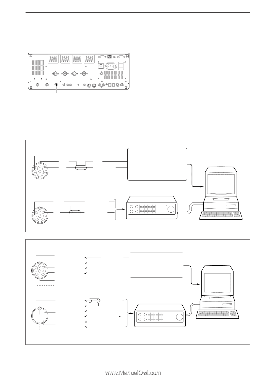
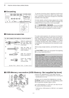
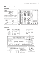
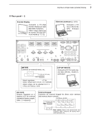
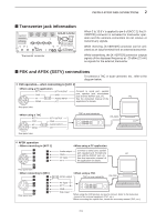
2 INSTALLATION AND CONNECTIONS ■ Transverter jack information Transverter connector When 2 to 13.8 V is applied to pin 6 of [ACC 2], the [XVERTER] connector is activated for transverter operation and the antenna connectors do not receive or transmit any signals. While receiving, [X-VERTER] connector can be activated as an input terminal from an external transverter. While transmitting, the [X-VERTER] connector outputs signals of the displayed frequency at -20 dBm (22 mV) as signals for the external transverter. ■ FSK and AFSK (SSTV) connections To connect a TNC or scan converter, etc., refer to the diagram below. D FSK operation- when connecting to [ACC 1] • When using a PC application RTTY RTTY OUTPUT Connect to serial port, parallel 2 45 GND AF GND AUDIO INPUT port, speaker jack, microphone jack and line IN/OUT jack, etc. See the instruction manual of the PC 183 67 SEND PTT application for details. Rear panel view • When using a TNC RTTY GND 2 45 183 67 AF SEND Rear panel view RTTY OUTPUT GND AUDIO INPUT PTT TNC or scan converter RS-232C D AFSK operation • When connecting to [ACC 1] z z x x 2 45 c c 183 67 v v b n† Rear panel view • When connecting to [MIC] z z c x qu x c wiy b v ert b v* n† n† Rear panel view • When using a PC application Audio output Connect to serial port, parallel GND port, speaker jack, microphone jack and line IN/OUT jack, etc. PC AF input See the instruction manual of PTT the application for details. • When using a TNC AFSK output TNC or scan converter RS-232C AF input PTT* GND SQL input† *When using the VOX function, no need to connect. Refer to the instruction manual of the external equipment (TNC, etc.). †When connecting the squelch line, consult the necessary manual (TNC, etc.). 2-9
-
 1
1 -
2
-
3
-
4
-
5
-
6
-
7
-
8
-
9
-
10
-
11
-
12
-
13
-
14
-
15
-
16
-
17
-
18
-
19
-
20
-
21
-
22
-
23
-
24
-
25
-
26
-
27
-
28
-
29
-
 30
30 -
 31
31 -
 32
32 -
 33
33 -
 34
34 -
 35
35 -
 36
36 -
 37
37 -
 38
38 -
 39
39 -
 40
40 -
41
-
42
-
43
-
44
-
45
-
46
-
47
-
48
-
49
-
50
-
51
-
52
-
53
-
54
-
55
-
56
-
57
-
58
-
59
-
60
-
61
-
62
-
63
-
64
-
65
-
66
-
67
-
68
-
69
-
70
-
71
-
72
-
73
-
74
-
75
-
76
-
77
-
78
-
79
-
80
-
81
-
82
-
83
-
84
-
85
-
86
-
87
-
88
-
89
-
90
-
91
-
92
-
93
-
94
-
95
-
96
-
97
-
98
-
99
-
100
-
101
-
102
-
103
-
104
-
105
-
106
-
107
-
108
-
109
-
110
-
111
-
112
-
113
-
114
-
115
-
116
-
117
-
118
-
119
-
120
-
121
-
122
-
123
-
124
-
125
-
126
-
127
-
128
-
129
-
130
-
131
-
132
-
133
-
134
-
135
-
136
-
137
-
138
-
139
-
140
-
141
-
142
-
143
-
144
-
145
-
146
-
147
-
148
-
149
-
150
-
151
-
152
-
153
-
154
-
155
-
156
-
157
-
158
-
159
-
160
-
161
-
162
-
163
-
164
-
165
-
166
-
167
-
168
-
169
-
170
-
171
-
172
-
173
-
174
-
175
-
176
-
177
-
178
-
179
-
180
-
181
-
182
-
183
-
184
-
185
-
186
-
187
-
188
-
189
-
190
-
191
-
192
-
193
-
194
-
195
-
196
-
197
-
198
-
199
-
200
-
201
-
202
-
203
-
204
-
205
-
206
-
207
-
208
-
209
-
210
-
211
-
212
-
213
-
214
-
215
-
216
 |
 |