Icom IC-7700 Instruction Manual - Page 36
Microphone connector information, Microphones
 |
View all Icom IC-7700 manuals
Add to My Manuals
Save this manual to your list of manuals |
Page 36 highlights
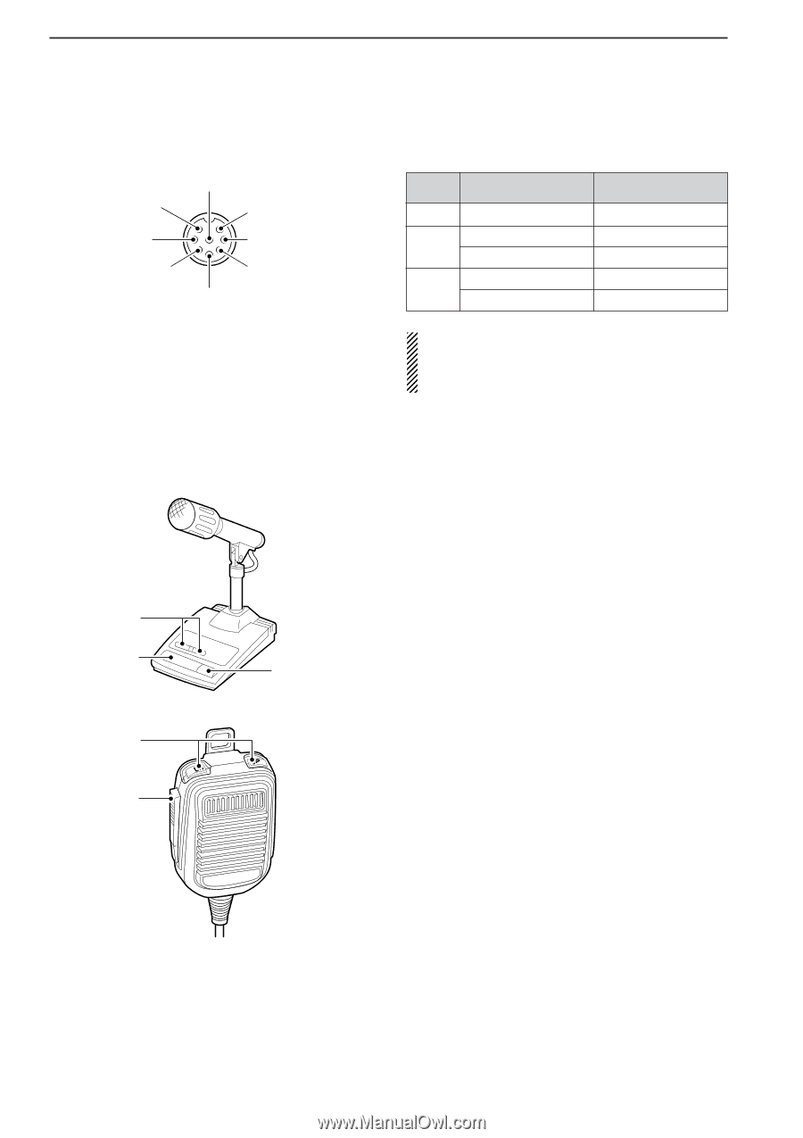
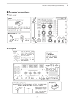
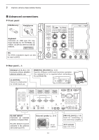
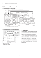
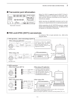
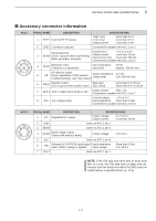
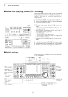
2 INSTALLATION AND CONNECTIONS ■ Microphone connector information (Front panel view) q Microphone input w +8 V DC output e Frequency up/down i AF output (varies with [AF]) u GND (Microphone ground) y GND (PTT ground) t PTT r Squelch switch [MIC] Pin No. FUNCTION w +8 V DC output Frequency up e Frequency down Squelch open r Squelch closed DESCRIPTION Max. 10 mA Ground Ground through 470 Ω "Low" level "High" level CAUTION: DO NOT short pin 2 to ground as this can damage the internal 8 V regulator. DC voltage is applied to pin 1 for microphone operation. Use caution when using a non-Icom microphone. ■ Microphones (options) D SM-20 q w e D HM-36 q q UP/DOWN SWITCHES [UP]/[DN] Change the selected readout frequency or memory channel. • Pressing a switch continuously changes the frequency or memory channel number continuously. • While pushing [XFC], the transmit readout frequency can be controlled while in split frequency operation. • The [UP]/[DN] switch can simulate a key paddle. Preset in the keyer set mode. (p. 4-12) w PTT SWITCH Push and hold to transmit; release to receive. e PTT LOCK SWITCH (available for SM-20 only) Push to toggle between transmit and receive. w 2-10
-
 1
1 -
2
-
3
-
4
-
5
-
6
-
7
-
8
-
9
-
10
-
11
-
12
-
13
-
14
-
15
-
16
-
17
-
18
-
19
-
20
-
21
-
22
-
23
-
24
-
25
-
26
-
27
-
28
-
29
-
30
-
 31
31 -
 32
32 -
 33
33 -
 34
34 -
 35
35 -
 36
36 -
 37
37 -
 38
38 -
 39
39 -
 40
40 -
 41
41 -
42
-
43
-
44
-
45
-
46
-
47
-
48
-
49
-
50
-
51
-
52
-
53
-
54
-
55
-
56
-
57
-
58
-
59
-
60
-
61
-
62
-
63
-
64
-
65
-
66
-
67
-
68
-
69
-
70
-
71
-
72
-
73
-
74
-
75
-
76
-
77
-
78
-
79
-
80
-
81
-
82
-
83
-
84
-
85
-
86
-
87
-
88
-
89
-
90
-
91
-
92
-
93
-
94
-
95
-
96
-
97
-
98
-
99
-
100
-
101
-
102
-
103
-
104
-
105
-
106
-
107
-
108
-
109
-
110
-
111
-
112
-
113
-
114
-
115
-
116
-
117
-
118
-
119
-
120
-
121
-
122
-
123
-
124
-
125
-
126
-
127
-
128
-
129
-
130
-
131
-
132
-
133
-
134
-
135
-
136
-
137
-
138
-
139
-
140
-
141
-
142
-
143
-
144
-
145
-
146
-
147
-
148
-
149
-
150
-
151
-
152
-
153
-
154
-
155
-
156
-
157
-
158
-
159
-
160
-
161
-
162
-
163
-
164
-
165
-
166
-
167
-
168
-
169
-
170
-
171
-
172
-
173
-
174
-
175
-
176
-
177
-
178
-
179
-
180
-
181
-
182
-
183
-
184
-
185
-
186
-
187
-
188
-
189
-
190
-
191
-
192
-
193
-
194
-
195
-
196
-
197
-
198
-
199
-
200
-
201
-
202
-
203
-
204
-
205
-
206
-
207
-
208
-
209
-
210
-
211
-
212
-
213
-
214
-
215
-
216
 |
 |