Icom IC-7700 Instruction Manual - Page 201
Receiver, Antenna tuner - power loss
 |
View all Icom IC-7700 manuals
Add to My Manuals
Save this manual to your list of manuals |
Page 201 highlights
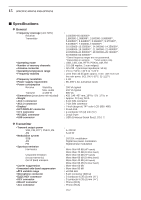
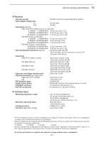
15 SPECIFICATIONS AND OPTIONS D Receiver • Receive system : Double conversion superheterodyne system • Intermediate frequencies : 1st 64.455 MHz 2nd 36 kHz • Sensitivity (typical) : SSB, CW, RTTY (BW=2.4 kHz, 10 dB S/N) 0.100000- 1.799999 MHz 0.5 µV (pre-amp 1 ON) 1.800000- 29.990000 MHz 0.16 µV (pre-amp 1 ON) 50.000000- 54.000000 MHz 0.13 µV (pre-amp 2 ON) AM (BW=6 kHz, 10 dB S/N) 0.100000- 1.799999 MHz 6.3 µV (pre-amp 1 ON) 1.800000- 29.990000 MHz 2 µV (pre-amp 1 ON) 50.000000- 54.000000 MHz 1 µV (pre-amp 2 ON) FM (BW=15 kHz, 12 dB SINAD) 28.000000- 29.990000 MHz 0.5 µV (pre-amp 1 ON) 50.000000- 54.000000 MHz 0.32 µV (pre-amp 2 ON) • Internal Modulate Distortion (typical) : Dynamic range 109 dB (at 14.100 MHz, 100 kHz separation, pre-amp OFF, CW mode; BW=500 Hz) • Selectivity : SSB, RTTY (BW=2.4 kHz) More than 2.4 kHz/-3 dB Less than 3.6 kHz/-60 dB CW (BW=500 Hz) More than 500 Hz/-3 dB Less than 700 Hz/-60 dB AM (BW=6 kHz) More than 6.0 kHz/-3 dB Less than 15.0 kHz/-60 dB FM (BW=15 kHz) More than 12.0 kHz/-6 dB Less than 20.0 kHz/-60 dB • Spurious and image rejection ratio : More than 70 dB • Squelch sensitivity (pre-amp OFF) : SSB, CW, RTTY, PSK31 Less than 5.6 µV FM Less than 1 µV • RIT variable range : ±9.999 kHz • Audio output power : More than 2.6 W at 10% distortion with an 8 Ω load • PHONES connector : 3-conductor 6.35 (d) mm (1⁄4″) • EXT-SP connectors : 2-conductor 3.5 (d) mm (1⁄8″)/8 Ω D Antenna tuner • Matching impedance range • Minimum operating input • Tuning accuracy • Insertion loss (after tuning) : 16.7 to 150 Ω unbalanced (HF bands; VSWR better than 3:1) 20 to 125 Ω unbalanced (50 MHz band; VSWR better than 2.5:1) : 8 W (HF bands) 15 W (50 MHz band) : VSWR 1.5:1 or less : Less than 1.0 dB *The LCD display may have cosmetic imperfections that appear as small or dark spots. This is not a malfunction or defect, but a normal characteristic of LCD displays. Spurious signals may be received near the following frequencies. These are made in the internal circuit and does not indicate a transceiver malfunction. • 0.15 MHz • 0.23 MHz 0.31 MHz • 10 MHz Spurious signals may be displayed on the spectrum scope screen regardless of the transceiver's state (Tx or Rx). They are generated in the scope circuit. This does not indicate a transceiver malfunction. All stated specifications are typical and subject to change without notice or obligation. 15-3
-
 1
1 -
2
-
3
-
4
-
5
-
6
-
7
-
8
-
9
-
10
-
11
-
12
-
13
-
14
-
15
-
16
-
17
-
18
-
19
-
20
-
21
-
22
-
23
-
24
-
25
-
26
-
27
-
28
-
29
-
30
-
31
-
32
-
33
-
34
-
35
-
36
-
37
-
38
-
39
-
40
-
41
-
42
-
43
-
44
-
45
-
46
-
47
-
48
-
49
-
50
-
51
-
52
-
53
-
54
-
55
-
56
-
57
-
58
-
59
-
60
-
61
-
62
-
63
-
64
-
65
-
66
-
67
-
68
-
69
-
70
-
71
-
72
-
73
-
74
-
75
-
76
-
77
-
78
-
79
-
80
-
81
-
82
-
83
-
84
-
85
-
86
-
87
-
88
-
89
-
90
-
91
-
92
-
93
-
94
-
95
-
96
-
97
-
98
-
99
-
100
-
101
-
102
-
103
-
104
-
105
-
106
-
107
-
108
-
109
-
110
-
111
-
112
-
113
-
114
-
115
-
116
-
117
-
118
-
119
-
120
-
121
-
122
-
123
-
124
-
125
-
126
-
127
-
128
-
129
-
130
-
131
-
132
-
133
-
134
-
135
-
136
-
137
-
138
-
139
-
140
-
141
-
142
-
143
-
144
-
145
-
146
-
147
-
148
-
149
-
150
-
151
-
152
-
153
-
154
-
155
-
156
-
157
-
158
-
159
-
160
-
161
-
162
-
163
-
164
-
165
-
166
-
167
-
168
-
169
-
170
-
171
-
172
-
173
-
174
-
175
-
176
-
177
-
178
-
179
-
180
-
181
-
182
-
183
-
184
-
185
-
186
-
187
-
188
-
189
-
190
-
191
-
192
-
193
-
194
-
195
-
 196
196 -
 197
197 -
 198
198 -
 199
199 -
 200
200 -
 201
201 -
 202
202 -
 203
203 -
 204
204 -
 205
205 -
 206
206 -
207
-
208
-
209
-
210
-
211
-
212
-
213
-
214
-
215
-
216
 |
 |