Kenwood TS-990S Operation Manual - Page 259
Configuring The I/o Signals For The Optical Digital Connector, Configuring The Input Audio Level
 |
View all Kenwood TS-990S manuals
Add to My Manuals
Save this manual to your list of manuals |
Page 259 highlights
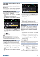
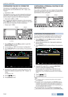
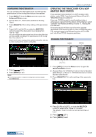
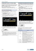
USEFUL FUNCTIONS 16 CONFIGURING THE I/O SIGNALS FOR THE OPTICAL DIGITAL CONNECTOR If you connect an external device, such as a PC, to the OPTICAL IN and OPTICAL OUT connectors on the rear panel, you can configure the level of signals modulated or reproduced in the external device or the level of signals processed in an equalizer. From the OPTICAL OUT connector, the main band received audio is available on the left channel, and the sub band received audio is available on the right channel. CONFIGURING THE INPUT AUDIO LEVEL If you connect an external device to the OPTICAL IN terminal on the rear panel, you can configure the audio signal input level. 1 Select Group No. 7, "Rear Connectors", from the Menu screen. 2 Access Menu 07, "Optical: Audio Input Level". 3 Press [SELECT] (F4) to allow editing of the parameter box. 4 Press [-] (F4) and [+] (F5), or rotate the MULTI/CH control to select the audio signal output level for the main band from the available range between "0" and "100". The default is "100". 5 Press [ ] (F1). 6 Press [MENU] to exit. Note: ◆◆The OPTICAL OUT connector conforms to the sampling frequency of 48 kHz, and to the number of bits of 24 bits. 4 Press [-] (F4) or [+] (F5), or rotate MULTI/CH control to select the input level from the available range between "0" and "100". The default is "50". 5 Press [ ] (F1). 6 Press [MENU] to exit. Note: ◆◆You can configure the desired input audio according to the transmission method. {page 9-1} ◆◆If you assign Data Send to a PF key, you can transmit the signal from the configured modulation line. {page 9-1} ◆◆The OPTICAL IN connector conforms to the sampling frequency of 44.1 kHz and 48 kHz, and to the number of bits of 16 bits and 24 bits. CONFIGURING THE OUTPUT AUDIO LEVEL If you connect an external device to the OPTICAL OUT terminal on the rear panel, you can configure the audio signal output level. 1 Select Group No. 7, "Rear Connectors", from the Menu screen. 2 Access Menu 12, "Optical: Audio Output Level (Main Band)" or Menu 13, "Optical: Audio Output Level (Sub Band)". 3 Press [SELECT] (F4) to allow editing of the parameter box. Selecting the Audio Output Format FROM THE OPTICAL OUT Connector You can select the output format of the received audio sent from the OPTICAL OUT connector on the rear panel. With the default configuration, the received audio of the main band is an output for the left channel, and the received audio of the sub band is an output for the right channel. 1 Select Group No. 7, "Rear Connectors", from the Menu screen. 2 Access Menu 18, "Optical: Audio Output Configuration". 3 Press [SELECT] (F4) to allow editing of the parameter box. 4 Press [-] (F4) or [+] (F5), or rotate the MULTI/CH control to select "Normal", "Reversed", or "Mixed". The default is "Normal". 5 Press [ ] (F1). 6 Press [MENU] to exit. Note: ◆◆Output audios vary depending on the parameter as follows. Parameter Left Channel Right Channel Normal Reversed Mixed Received audio of the main band Received audio of the sub band Received audio of the sub Received audio of the main band band Mixed audio of the receive Mixed audio of the receive signals of the main band signals of the main band and the sub band and the sub band Contents Index 16-19
-
 1
1 -
2
-
3
-
4
-
5
-
6
-
7
-
8
-
9
-
10
-
11
-
12
-
13
-
14
-
15
-
16
-
17
-
18
-
19
-
20
-
21
-
22
-
23
-
24
-
25
-
26
-
27
-
28
-
29
-
30
-
31
-
32
-
33
-
34
-
35
-
36
-
37
-
38
-
39
-
40
-
41
-
42
-
43
-
44
-
45
-
46
-
47
-
48
-
49
-
50
-
51
-
52
-
53
-
54
-
55
-
56
-
57
-
58
-
59
-
60
-
61
-
62
-
63
-
64
-
65
-
66
-
67
-
68
-
69
-
70
-
71
-
72
-
73
-
74
-
75
-
76
-
77
-
78
-
79
-
80
-
81
-
82
-
83
-
84
-
85
-
86
-
87
-
88
-
89
-
90
-
91
-
92
-
93
-
94
-
95
-
96
-
97
-
98
-
99
-
100
-
101
-
102
-
103
-
104
-
105
-
106
-
107
-
108
-
109
-
110
-
111
-
112
-
113
-
114
-
115
-
116
-
117
-
118
-
119
-
120
-
121
-
122
-
123
-
124
-
125
-
126
-
127
-
128
-
129
-
130
-
131
-
132
-
133
-
134
-
135
-
136
-
137
-
138
-
139
-
140
-
141
-
142
-
143
-
144
-
145
-
146
-
147
-
148
-
149
-
150
-
151
-
152
-
153
-
154
-
155
-
156
-
157
-
158
-
159
-
160
-
161
-
162
-
163
-
164
-
165
-
166
-
167
-
168
-
169
-
170
-
171
-
172
-
173
-
174
-
175
-
176
-
177
-
178
-
179
-
180
-
181
-
182
-
183
-
184
-
185
-
186
-
187
-
188
-
189
-
190
-
191
-
192
-
193
-
194
-
195
-
196
-
197
-
198
-
199
-
200
-
201
-
202
-
203
-
204
-
205
-
206
-
207
-
208
-
209
-
210
-
211
-
212
-
213
-
214
-
215
-
216
-
217
-
218
-
219
-
220
-
221
-
222
-
223
-
224
-
225
-
226
-
227
-
228
-
229
-
230
-
231
-
232
-
233
-
234
-
235
-
236
-
237
-
238
-
239
-
240
-
241
-
242
-
243
-
244
-
245
-
246
-
247
-
248
-
249
-
250
-
251
-
252
-
253
-
 254
254 -
 255
255 -
 256
256 -
 257
257 -
 258
258 -
 259
259 -
 260
260 -
 261
261 -
 262
262 -
 263
263 -
 264
264 -
265
-
266
-
267
-
268
-
269
-
270
-
271
-
272
-
273
-
274
-
275
-
276
-
277
-
278
-
279
-
280
-
281
-
282
-
283
-
284
-
285
-
286
-
287
-
288
-
289
-
290
-
291
-
292
-
293
-
294
-
295
-
296
-
297
-
298
-
299
-
300
 |
 |
