Kenwood TS-990S Operation Manual - Page 279
Troubleshooting, Calibrating The Internal Reference Frequency, Calibration Procedure, Frequency
 |
View all Kenwood TS-990S manuals
Add to My Manuals
Save this manual to your list of manuals |
Page 279 highlights
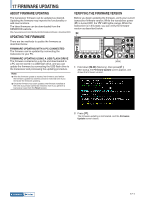
18 TROUBLESHOOTING CALIBRATING THE INTERNAL REFERENCE FREQUENCY The internal reference frequency of the transceiver was properly calibrated at the factory. However, if the reference frequency needs to be calibrated due to any reason such as extended use, the internal reference frequency can be calibrated by receiving a standard wave signal such as VVWH (Hawaii), VVH (Colorado), BPM (Xian), or others. At first, follow the procedure described below to enable the transceiver to receive the standard wave signal. The procedure below describes the procedure when the pitch frequency is 700 Hz.
-
 1
1 -
2
-
3
-
4
-
5
-
6
-
7
-
8
-
9
-
10
-
11
-
12
-
13
-
14
-
15
-
16
-
17
-
18
-
19
-
20
-
21
-
22
-
23
-
24
-
25
-
26
-
27
-
28
-
29
-
30
-
31
-
32
-
33
-
34
-
35
-
36
-
37
-
38
-
39
-
40
-
41
-
42
-
43
-
44
-
45
-
46
-
47
-
48
-
49
-
50
-
51
-
52
-
53
-
54
-
55
-
56
-
57
-
58
-
59
-
60
-
61
-
62
-
63
-
64
-
65
-
66
-
67
-
68
-
69
-
70
-
71
-
72
-
73
-
74
-
75
-
76
-
77
-
78
-
79
-
80
-
81
-
82
-
83
-
84
-
85
-
86
-
87
-
88
-
89
-
90
-
91
-
92
-
93
-
94
-
95
-
96
-
97
-
98
-
99
-
100
-
101
-
102
-
103
-
104
-
105
-
106
-
107
-
108
-
109
-
110
-
111
-
112
-
113
-
114
-
115
-
116
-
117
-
118
-
119
-
120
-
121
-
122
-
123
-
124
-
125
-
126
-
127
-
128
-
129
-
130
-
131
-
132
-
133
-
134
-
135
-
136
-
137
-
138
-
139
-
140
-
141
-
142
-
143
-
144
-
145
-
146
-
147
-
148
-
149
-
150
-
151
-
152
-
153
-
154
-
155
-
156
-
157
-
158
-
159
-
160
-
161
-
162
-
163
-
164
-
165
-
166
-
167
-
168
-
169
-
170
-
171
-
172
-
173
-
174
-
175
-
176
-
177
-
178
-
179
-
180
-
181
-
182
-
183
-
184
-
185
-
186
-
187
-
188
-
189
-
190
-
191
-
192
-
193
-
194
-
195
-
196
-
197
-
198
-
199
-
200
-
201
-
202
-
203
-
204
-
205
-
206
-
207
-
208
-
209
-
210
-
211
-
212
-
213
-
214
-
215
-
216
-
217
-
218
-
219
-
220
-
221
-
222
-
223
-
224
-
225
-
226
-
227
-
228
-
229
-
230
-
231
-
232
-
233
-
234
-
235
-
236
-
237
-
238
-
239
-
240
-
241
-
242
-
243
-
244
-
245
-
246
-
247
-
248
-
249
-
250
-
251
-
252
-
253
-
254
-
255
-
256
-
257
-
258
-
259
-
260
-
261
-
262
-
263
-
264
-
265
-
266
-
267
-
268
-
269
-
270
-
271
-
272
-
273
-
 274
274 -
 275
275 -
 276
276 -
 277
277 -
 278
278 -
 279
279 -
 280
280 -
 281
281 -
 282
282 -
 283
283 -
 284
284 -
285
-
286
-
287
-
288
-
289
-
290
-
291
-
292
-
293
-
294
-
295
-
296
-
297
-
298
-
299
-
300
 |
 |

18-1
18 TROUBLESHOOTING
Index
Contents
CALIBRATING THE INTERNAL REFERENCE
FREQUENCY
The internal reference frequency of the transceiver was
properly calibrated at the factory. However, if the reference
frequency needs to be calibrated due to any reason such
as extended use, the internal reference frequency can be
calibrated by receiving a standard wave signal such as
VVWH (Hawaii), VVH (Colorado), BPM (Xian), or others.
At first, follow the procedure described below to enable
the transceiver to receive the standard wave signal. The
procedure below describes the procedure when the pitch
frequency is 700 Hz.
[CW/CW-R]
[RIT]
[VOX/SEL]
[AF](M)
[CW PITCH]
[HI/SHIFT]
[LO/WIDTH]
1
Press
[CW/ CW-R]
to select CW mode.
2
Press
[RIT]
to disable the RIT function.
The "RIT" LED turns Off.
3
Press
[VOL/SEL]
to enable break-in.
•
If semi break-in is enabled, press
[VOX/SEL]
to disable
semi break in.
•
If full break-in is enabled, press
[VOX/SEL]
to disable full
break in.
•
The "VOX" LED turns Off.
4
Rotate the
AF
control to select the 12 o'clock position.
5
Rotate the
CW PITCH
control to adjust the pitch to be
legible.
You can rotate the
CW PITCH
control until the pitch
frequency, displayed on the sub-scope center with the sub-
screen, reaches 700 Hz.
6
Rotate the
LO/WIDTH
control or the
HI/SHIFT
control.
You can rotate the
HI/SHIFT
control until the shift frequency
(SHIFT), displayed on the sub-scope with the sub-screen,
reaches a value of 0, and the
LO/WIDTH
control until the
bandwidth (WIDTH) reaches a value of 1000.
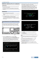
SUB-SCREEN
Note:
◆
Refer to "CONFIGURING THE REF I/O CONNECTOR" for the
configuration of the REF I/O connector.
{page 16-22}
CALIBRATION PROCEDURE
After the calibration is complete, follow the procedure
below to configure the internal reference frequency.
[CW/CW-R]
[RIT]
[VOX/SEL]
[AF](M)
[CW PITCH]
[HI/SHIFT]
[LO/WIDTH]
1
Receive a standard wave signal on the main band.
To receive the 10 MHz standard wave signal, rotate the
Tuning
control to select exactly "10.000.00".
The 700 Hz beat sounds.
f
AF
=
f
reference
+ 700
[Hz]
x
f
display [MHz]
15.6
[MHz]
f
reference
Shifts from Reference Frequency
The received beat can be audible on the CW pitch frequency.
2
Press
[ADV.]
(F) from the
Menu
screen to open the
Advanced Menu
screen.
3
Access Menu 05, "Reference Oscillator Calibration".
4
Press
[SELECT]
(F4) to allow editing of the parameter
box.
5
Press
[CAL.T]
(F7).
The 700 Hz sidetone for calibration is generated. A double-
beat occurs due to the difference of two frequencies by the
sidetone and the received audio crossing each other.
If the double-beat cannot be heard clearly, rotate the
AF
control to adjust the received audio level or the
MONITOR
control to adjust the sidetone audio level.
f
sidetone
= 700
[Hz]
8
[ppm]
‒
+
(700
0.006
[Hz]
)
‒
+