Kenwood TS-990S Operation Manual - Page 272

Controlling The Linear Amplifier At 50 Mhz, Remote, Adv.], Advanced Menu, Select], Multi/ch, Menu]

Page 272 highlights

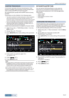
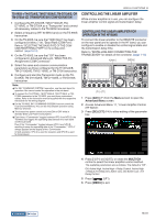
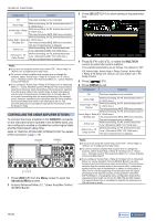
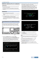
16 USEFUL FUNCTIONS Configuration Operation Off The linear amplifier is not controlled. Active High While transmitting, the RL terminal becomes 12 V. (10mA max.) Active High + Relay Control While transmitting, the RL terminal becomes 12 V. (10mA max.) The relay terminals (MKE, BRK) are controlled. While transmitting, the RL terminal becomes 12 Active High + Relay & V. (10mA max.) TX Delay Ctrl The relay terminals (MKE, BRK) are controlled. Active Low The start of transmission is delayed. While transmitting, the RL terminal becomes "Low". (Shorted to GND, 15V 10mA max.) Active Low + TX Delay Control While transmitting, the RL terminal becomes "Low". (Shorted to GND, 15V 10mA max.) The start of transmission is delayed. Note: ◆◆If you are not using the control relay, select "Off", "Active High", or "Active Low" to suppress the relay noise. ◆◆To connect a linear amplifier that requires time to change the antenna, select "Active High + Relay & TX Delay Ctrl" or "Active Low + TX Delay Control" from Advanced Menu 11, "Linear Amplifier Control (HF Band)". ◆◆If you configure "Active High + Relay & TX Delay Ctrl" in Advanced Menu 11, "Linear Amplifier Control (HF Band)", the relay functions when the transceiver starts transmitting. If the transceiver switches from the receive state to the transmit state, a delay time applied until the start of transmission is added. Also, it normally takes 10 ms to start transmitting after the signal processing in the transmit circuit; however, considering the operation with the linear amplifier, the transmit delay time needs to be extended to 25 ms. The transmit delay time is not added to operate the transceiver in CW full break-in mode. CONTROLLING THE LINEAR AMPLIFIER AT 50 MHz To connect the linear amplifier to the REMOTE connector on the rear panel and to operate in the 50 MHz band, you can configure to enable or disable the control signal state and the transmission delay time. Refer to "INSTALLATION AND CONNECTION" for details of the connector. {page 1-10} '

  • 1
  • 2
  • 3
  • 4
  • 5
  • 6
  • 7
  • 8
  • 9
  • 10
  • 11
  • 12
  • 13
  • 14
  • 15
  • 16
  • 17
  • 18
  • 19
  • 20
  • 21
  • 22
  • 23
  • 24
  • 25
  • 26
  • 27
  • 28
  • 29
  • 30
  • 31
  • 32
  • 33
  • 34
  • 35
  • 36
  • 37
  • 38
  • 39
  • 40
  • 41
  • 42
  • 43
  • 44
  • 45
  • 46
  • 47
  • 48
  • 49
  • 50
  • 51
  • 52
  • 53
  • 54
  • 55
  • 56
  • 57
  • 58
  • 59
  • 60
  • 61
  • 62
  • 63
  • 64
  • 65
  • 66
  • 67
  • 68
  • 69
  • 70
  • 71
  • 72
  • 73
  • 74
  • 75
  • 76
  • 77
  • 78
  • 79
  • 80
  • 81
  • 82
  • 83
  • 84
  • 85
  • 86
  • 87
  • 88
  • 89
  • 90
  • 91
  • 92
  • 93
  • 94
  • 95
  • 96
  • 97
  • 98
  • 99
  • 100
  • 101
  • 102
  • 103
  • 104
  • 105
  • 106
  • 107
  • 108
  • 109
  • 110
  • 111
  • 112
  • 113
  • 114
  • 115
  • 116
  • 117
  • 118
  • 119
  • 120
  • 121
  • 122
  • 123
  • 124
  • 125
  • 126
  • 127
  • 128
  • 129
  • 130
  • 131
  • 132
  • 133
  • 134
  • 135
  • 136
  • 137
  • 138
  • 139
  • 140
  • 141
  • 142
  • 143
  • 144
  • 145
  • 146
  • 147
  • 148
  • 149
  • 150
  • 151
  • 152
  • 153
  • 154
  • 155
  • 156
  • 157
  • 158
  • 159
  • 160
  • 161
  • 162
  • 163
  • 164
  • 165
  • 166
  • 167
  • 168
  • 169
  • 170
  • 171
  • 172
  • 173
  • 174
  • 175
  • 176
  • 177
  • 178
  • 179
  • 180
  • 181
  • 182
  • 183
  • 184
  • 185
  • 186
  • 187
  • 188
  • 189
  • 190
  • 191
  • 192
  • 193
  • 194
  • 195
  • 196
  • 197
  • 198
  • 199
  • 200
  • 201
  • 202
  • 203
  • 204
  • 205
  • 206
  • 207
  • 208
  • 209
  • 210
  • 211
  • 212
  • 213
  • 214
  • 215
  • 216
  • 217
  • 218
  • 219
  • 220
  • 221
  • 222
  • 223
  • 224
  • 225
  • 226
  • 227
  • 228
  • 229
  • 230
  • 231
  • 232
  • 233
  • 234
  • 235
  • 236
  • 237
  • 238
  • 239
  • 240
  • 241
  • 242
  • 243
  • 244
  • 245
  • 246
  • 247
  • 248
  • 249
  • 250
  • 251
  • 252
  • 253
  • 254
  • 255
  • 256
  • 257
  • 258
  • 259
  • 260
  • 261
  • 262
  • 263
  • 264
  • 265
  • 266
  • 267
  • 268
  • 269
  • 270
  • 271
  • 272
  • 273
  • 274
  • 275
  • 276
  • 277
  • 278
  • 279
  • 280
  • 281
  • 282
  • 283
  • 284
  • 285
  • 286
  • 287
  • 288
  • 289
  • 290
  • 291
  • 292
  • 293
  • 294
  • 295
  • 296
  • 297
  • 298
  • 299
  • 300

16 USEFUL FUNCTIONS
16-32
Index
Contents
Configuration
Operation
Off
The linear amplifier is not controlled.
Active High
While transmitting, the RL terminal becomes 12
V. (10mA max.)
Active High + Relay
Control
While transmitting, the RL terminal becomes 12
V. (10mA max.)
The relay terminals (MKE, BRK) are controlled.
Active High + Relay &
TX Delay Ctrl
While transmitting, the RL terminal becomes 12
V. (10mA max.)
The relay terminals (MKE, BRK) are controlled.
The start of transmission is delayed.
Active Low
While transmitting, the RL terminal becomes
"Low". (Shorted to GND, 15V 10mA max.)
Active Low + TX
Delay Control
While transmitting, the RL terminal becomes
"Low". (Shorted to GND, 15V 10mA max.)
The start of transmission is delayed.
Note:
If you are not using the control relay, select "Off", "Active High", or
"Active Low" to suppress the relay noise.
To connect a linear amplifier that requires time to change the
antenna, select "Active High + Relay & TX Delay Ctrl" or "Active
Low + TX Delay Control" from Advanced Menu 11, "Linear Amplifier
Control (HF Band)".
◆ If you configure "Active High + Relay & TX Delay Ctrl" in Advanced
Menu 11, "Linear Amplifier Control (HF Band)", the relay functions
when the transceiver starts transmitting. If the transceiver switches
from the receive state to the transmit state, a delay time applied
until the start of transmission is added. Also, it normally takes 10
ms to start transmitting after the signal processing in the transmit
circuit; however, considering the operation with the linear amplifier,
the transmit delay time needs to be extended to 25 ms. The
transmit delay time is not added to operate the transceiver in CW
full break-in mode.
CONTROLLING THE LINEAR AMPLIFIER AT 50 MH
Z
To connect the linear amplifier to the
REMOTE
connector
on the rear panel and to operate in the 50 MHz band, you
can configure to enable or disable the control signal state
and the transmission delay time.
Refer to "INSTALLATION AND CONNECTION" for details
of the connector.
{page 1-10}
[F1]~[F7]
[MENU]
F[ADV.]
1
Press
[ADV.]
(F) from the
Menu
screen to open the
Advanced Menu
screen.
2
Access Advanced Menu 12, "Linear Amplifier Control
(50 MHz Band)".
3
Press
[SELECT]
(F4) to allow editing of the parameter
box.
4
Press
[-]
(F4) or
[+]
(F5), or rotate the
MULTI/CH
control to select the control method.
The available parameters are as follows. The default is "Off".
Off, Active High, Active High + Relay Control, Active High
+ Relay & TX Delay Ctrl, Active Low, and Active Low + TX
Delay Control
5
Press
[
]
(F1).
6
Press
[MENU]
to exit.
Configuration
Operation
Off
The linear amplifier is not controlled.
Active High
While transmitting, the RL terminal becomes 12
V. (10mA max.)
Active High + Relay
Control
While transmitting, the RL terminal becomes 12
V. (10mA max.)
The relay terminals (MKE, BRK) are controlled.
Active High + Relay &
TX Delay Ctrl
While transmitting, the RL terminal becomes 12
V. (10mA max.)
The relay terminals (MKE, BRK) are controlled.
The start of transmission is delayed.
Active Low
While transmitting, the RL terminal becomes
"Low".(Shorted to GND, 15V 10mA max.)
Active Low + TX
Delay Control
While transmitting, the RL terminal becomes
"Low". (Shorted to GND, 15V 10mA max.)
The start of transmission is delayed.
Note:
If you are not using the control relay, select "Off", "Active High", or
"Active Low" to suppress the relay noise.
To connect a linear amplifier that requires time to change the
antenna, select "Active High + Relay & TX Delay Ctrl" or "Active
Low + TX Delay Control" from Advanced Menu 12, "Linear Amplifier
Control (50 MHz Band)".
◆ If you configure "Active High + Relay & TX Delay Ctrl" in Advanced
Menu 12, "Linear Amplifier Control (50 MHz Band)", the relay
functions when the transceiver starts transmitting. If the transceiver
switches from the receive state to the transmit state, a delay time
applied until the start of transmission is added. In many cases, it
takes 10 ms until the beginning of transmission after the signal
processing in the transmit circuitry. In the operation other than
CW Full Break-in, changing the menu configuration extends the
response time to be 25 ms (45 ms for SSB, FM and AM modes).
The transmit delay time is not added to operate the transceiver in
CW full break-in mode.