Kenwood TS-990S Operation Manual - Page 264
Configuring The Sql Control Signal, Selecting The Msq/ssq Logic
 |
View all Kenwood TS-990S manuals
Add to My Manuals
Save this manual to your list of manuals |
Page 264 highlights
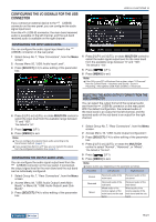
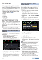
16 USEFUL FUNCTIONS CONFIGURING THE SQL CONTROL SIGNAL If you connect an external device, such as a TNC or PC, to the ACC 2 connector on the rear panel, you can configure the SQL control signal condition with the MSQ pin and SSQ pin of the ACC 2 connector. Refer to "INSTALLING AND CONNECTING THE TRANSCEIVER" for details of the connector. {page 1-11} SELECTING THE MSQ/SSQ LOGIC You can configure the logic of the SQL control signal of the MSQ pin and SSQ pin. 1 Press [ADV.] (F) from the Menu screen to open the Advanced Menu screen. 2 Access Menu 18, "MSQ Logic State" (Main band), or Menu 19, "SSQ Logic State" (Sub Band). 3 Press [SELECT] (F4) to allow editing of the parameter box. CONFIGURING THE MSQ/SSQ OUTPUT CONDITIONS You can configure the method to change the conditions of the SQL control signal transferred from the MSQ pin and SSQ pin. 1 Press [ADV.] (F) from the Menu screen to open the Advanced Menu screen. 2 Access Menu 20, "MSQ Reverse Condition" (Main band), or Menu 21, "SSQ Reverse Condition" (Sub Band). 3 Press [SELECT] (F4) to allow editing of the parameter box. 4 Press [-] (F4) or [+] (F5) to select "Low" or "Open". The default is "Low" for both the main band and the sub band. 5 Press [ ] (F1). 6 Press [MENU] to exit. Note: ◆◆The VoIP application installed in a PC detects the busy state even after the transceiver power ( ) has turned OFF, select "Open" for Menu 18, "MSQ Logic State" (Main Band), or Menu 19, "SSQ Logic State" (Sub Band). As well, you must configure the logic of the busy state detection in the VoIP application to be the same as the transceiver configurations. 4 Press [-] (F4) or [+] (F5), or rotate the MULTI/CH control to select the signal output conditions. Available parameters are "Busy", "Sql", "Send", "Busy-Send", "Sql-Send", and "Off". The default is "Sql" for both the main band and the sub band. 5 Press [ ] (F1). 6 Press [MENU] to exit. The SQL control signal is transferred from the MSQ pin and SSQ pin for the main band and sub band independently. Configured Value Operation Off Busy Sql Send Busy-Send Sql-Send Fixed at low (inactive). The SQL control signal becomes high (active) regardless of the matching status of the received CTCSS frequency. If the CTCSS signaling is active, the SQL control signal becomes high (active) when the received CTCSS frequency coincides with the CTCSS frequency configured for the transceiver. If the CTCSS signaling is inactive, the SQL control signal becomes high (active) when the CTCSS frequency is received, regardless of the matching status of the received CTCSS frequency. The SQL control signal becomes high while the transceiver is transmitting. The SQL control signal becomes high while the transceiver is transmitting and receiving. If "Sql" and "Send" are configured, the SQL control signal becomes high. 16-24 Index Contents
-
 1
1 -
2
-
3
-
4
-
5
-
6
-
7
-
8
-
9
-
10
-
11
-
12
-
13
-
14
-
15
-
16
-
17
-
18
-
19
-
20
-
21
-
22
-
23
-
24
-
25
-
26
-
27
-
28
-
29
-
30
-
31
-
32
-
33
-
34
-
35
-
36
-
37
-
38
-
39
-
40
-
41
-
42
-
43
-
44
-
45
-
46
-
47
-
48
-
49
-
50
-
51
-
52
-
53
-
54
-
55
-
56
-
57
-
58
-
59
-
60
-
61
-
62
-
63
-
64
-
65
-
66
-
67
-
68
-
69
-
70
-
71
-
72
-
73
-
74
-
75
-
76
-
77
-
78
-
79
-
80
-
81
-
82
-
83
-
84
-
85
-
86
-
87
-
88
-
89
-
90
-
91
-
92
-
93
-
94
-
95
-
96
-
97
-
98
-
99
-
100
-
101
-
102
-
103
-
104
-
105
-
106
-
107
-
108
-
109
-
110
-
111
-
112
-
113
-
114
-
115
-
116
-
117
-
118
-
119
-
120
-
121
-
122
-
123
-
124
-
125
-
126
-
127
-
128
-
129
-
130
-
131
-
132
-
133
-
134
-
135
-
136
-
137
-
138
-
139
-
140
-
141
-
142
-
143
-
144
-
145
-
146
-
147
-
148
-
149
-
150
-
151
-
152
-
153
-
154
-
155
-
156
-
157
-
158
-
159
-
160
-
161
-
162
-
163
-
164
-
165
-
166
-
167
-
168
-
169
-
170
-
171
-
172
-
173
-
174
-
175
-
176
-
177
-
178
-
179
-
180
-
181
-
182
-
183
-
184
-
185
-
186
-
187
-
188
-
189
-
190
-
191
-
192
-
193
-
194
-
195
-
196
-
197
-
198
-
199
-
200
-
201
-
202
-
203
-
204
-
205
-
206
-
207
-
208
-
209
-
210
-
211
-
212
-
213
-
214
-
215
-
216
-
217
-
218
-
219
-
220
-
221
-
222
-
223
-
224
-
225
-
226
-
227
-
228
-
229
-
230
-
231
-
232
-
233
-
234
-
235
-
236
-
237
-
238
-
239
-
240
-
241
-
242
-
243
-
244
-
245
-
246
-
247
-
248
-
249
-
250
-
251
-
252
-
253
-
254
-
255
-
256
-
257
-
258
-
 259
259 -
 260
260 -
 261
261 -
 262
262 -
 263
263 -
 264
264 -
 265
265 -
 266
266 -
 267
267 -
 268
268 -
 269
269 -
270
-
271
-
272
-
273
-
274
-
275
-
276
-
277
-
278
-
279
-
280
-
281
-
282
-
283
-
284
-
285
-
286
-
287
-
288
-
289
-
290
-
291
-
292
-
293
-
294
-
295
-
296
-
297
-
298
-
299
-
300
 |
 |
