Netgear WN203 User Manual - Page 12
Back Panel, 100/1000BASE-T Gigabit Ethernet RJ-45 LAN port with Auto Uplink Auto MDI-X - antenna
 |
View all Netgear WN203 manuals
Add to My Manuals
Save this manual to your list of manuals |
Page 12 highlights
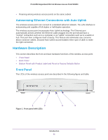
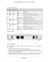
ProSAFE Single Band 802.11n Wireless Access Point WN203 Table 1. Front panel LEDs Item LED 1 2 Description Power Off Green Test Off Amber Blinking amber 3 LAN Off Amber Green 4 WLAN Off Blue Blinking Blue Power is off. Power is on. The wireless access point functions normally. The wireless access point is starting. After about one minute, the LED turns off. New firmware is being loaded. No link is detected on the LAN port. A 100 Mbps or 10 Mbps link is detected on the LAN port. A 1000 Mbps link is detected on the LAN port. The wireless LAN is not ready, or no wireless activity is detected. The wireless LAN is ready. Wireless activity is detected. Back Panel 1 2 3 Figure 2. Back panel 4 5 The back panel components of the wireless access point, from left to right, are described in the following list: 1. Reverse SMA connector for an optional 2.4 GHz antenna. 2. Console port for connecting to an optional console terminal. The port has an RJ-45 connector and supports the following settings: 115200 K default baud rate, (8) data bits, no (N) parity bit, and one (1) stop bit. 3. 10/100/1000BASE-T Gigabit Ethernet RJ-45 LAN port with Auto Uplink (Auto MDI-X) and IEEE 802.3af Power over Ethernet (PoE) support for connection to a switch or router. Introduction 12
-
 1
1 -
2
-
3
-
4
-
5
-
6
-
 7
7 -
 8
8 -
 9
9 -
 10
10 -
 11
11 -
 12
12 -
 13
13 -
 14
14 -
 15
15 -
 16
16 -
 17
17 -
18
-
19
-
20
-
21
-
22
-
23
-
24
-
25
-
26
-
27
-
28
-
29
-
30
-
31
-
32
-
33
-
34
-
35
-
36
-
37
-
38
-
39
-
40
-
41
-
42
-
43
-
44
-
45
-
46
-
47
-
48
-
49
-
50
-
51
-
52
-
53
-
54
-
55
-
56
-
57
-
58
-
59
-
60
-
61
-
62
-
63
-
64
-
65
-
66
-
67
-
68
-
69
-
70
-
71
-
72
-
73
-
74
-
75
-
76
-
77
-
78
-
79
-
80
-
81
-
82
-
83
-
84
-
85
-
86
-
87
-
88
-
89
-
90
-
91
-
92
-
93
-
94
-
95
-
96
-
97
-
98
-
99
-
100
-
101
-
102
-
103
-
104
-
105
-
106
-
107
-
108
-
109
-
110
-
111
-
112
-
113
-
114
-
115
-
116
-
117
-
118
-
119
-
120
-
121
-
122
-
123
-
124
-
125
-
126
-
127
-
128
-
129
-
130
-
131
-
132
-
133
 |
 |
