Netgear WN203 User Manual - Page 80
Apply, Enable Wireless Client Association, Optional Clear
 |
View all Netgear WN203 manuals
Add to My Manuals
Save this manual to your list of manuals |
Page 80 highlights
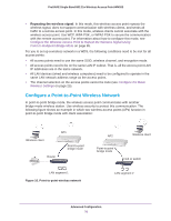
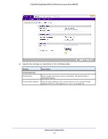
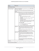
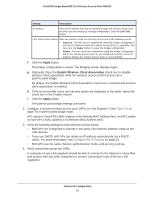
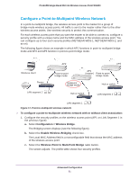
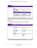
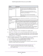
ProSAFE Single Band 802.11n Wireless Access Point WN203 Setting Description IP Address Enter an IP address that can be reached through the remote access point for which you are setting up a bridge configuration. Click the Link Test button. Link Test Process Status After one minute or less, the link test returns one of the following results: • Success. The link can be established using the bridge configuration, and the IP address behind the remote access point is reachable. You can click the Apply button to save the bridge configuration. • Failure. The link cannot be established using the bridge configuration. Either the remote access point is not configured correctly or the IP address behind the remote access point is not reachable. f. Click the Apply button. The bridge configuration is saved. The Bridging screen displays again. g. (Optional) Clear the Enable Wireless Client Association check box to disable wireless client association while the wireless access point functions as a point-to-point bridge. By default, the Enable Wireless Client Association check box is selected and wireless client association is enabled. h. If the correct profile name and security option are displayed in the table, select the check box in the Enable column. i. Click the Apply button. The point-to-point bridge settings are saved. 2. Configure a second wireless access point (AP2) on LAN Segment 2 (see Figure 16 on page 76) in point-to-point bridge mode. AP1 needs to have AP2's MAC address in its Remote MAC Address field, and AP2 needs to have AP1's MAC address in its Remote MAC Address field. 3. Verify the following settings for both wireless access points: • Both APs are configured to operate in the same LAN network address range as the LAN devices. • If you use DHCP, both APs can obtain an IP address automatically (as a DHCP client). For more information, see Configure the IP Settings on page 22. • Both APs use the same channel, authentication mode, and security settings. 4. Verify connectivity across the LANs. A computer on any LAN segment should be able to connect to the Internet or share files and printers with any other computers or servers connected to any of the two LAN segments. Advanced Configuration 80
-
 1
1 -
2
-
3
-
4
-
5
-
6
-
7
-
8
-
9
-
10
-
11
-
12
-
13
-
14
-
15
-
16
-
17
-
18
-
19
-
20
-
21
-
22
-
23
-
24
-
25
-
26
-
27
-
28
-
29
-
30
-
31
-
32
-
33
-
34
-
35
-
36
-
37
-
38
-
39
-
40
-
41
-
42
-
43
-
44
-
45
-
46
-
47
-
48
-
49
-
50
-
51
-
52
-
53
-
54
-
55
-
56
-
57
-
58
-
59
-
60
-
61
-
62
-
63
-
64
-
65
-
66
-
67
-
68
-
69
-
70
-
71
-
72
-
73
-
74
-
 75
75 -
 76
76 -
 77
77 -
 78
78 -
 79
79 -
 80
80 -
 81
81 -
 82
82 -
 83
83 -
 84
84 -
 85
85 -
86
-
87
-
88
-
89
-
90
-
91
-
92
-
93
-
94
-
95
-
96
-
97
-
98
-
99
-
100
-
101
-
102
-
103
-
104
-
105
-
106
-
107
-
108
-
109
-
110
-
111
-
112
-
113
-
114
-
115
-
116
-
117
-
118
-
119
-
120
-
121
-
122
-
123
-
124
-
125
-
126
-
127
-
128
-
129
-
130
-
131
-
132
-
133
 |
 |
