Panasonic AG-HPX600PJ Operating Instructions - Page 104
Thumbnail screen, Thumbnail Operations for Clips - Thumbnail operations
 |
View all Panasonic AG-HPX600PJ manuals
Add to My Manuals
Save this manual to your list of manuals |
Page 104 highlights
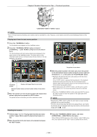
Chapter 6 Thumbnail Operations for Clips - Thumbnail operations Thumbnail screen Press the button to display the thumbnail screen on the viewfinder screen. Press the button again to return to the regular display. Also, when changing from the regular display to the thumbnail screen display, all clips will be displayed on the thumbnail screen. Also, press the button from the thumbnail screen to enable thumbnail menu operations. 2 1 17 16 3 4 5 9 10 6 7 18 8 19 11 12 13 14 15 Displayed only when the [EVF TYPE] item on the setting menu [DISPLAY SETUP] screen is set to [B/W]. 1 Display mode Displays the type of the thumbnail displayed on the screen, and the types of the other information screens. [ALL] [SAME FORMAT] [SELECT] [MARKER] [TEXT MEMO] [SLOT n] [UPDATING..] Displays all clips. Displays clips in the same format as the system format [SYSTEM MODE] item, and [REC FORMAT] item. For details on each item, refer to "Selecting recording signals" (page 48). Displays clips selected with the button. Displays clips with shot marks. Displays clips with text memo data. Displays clips in the specified P2 card. (n: indicates slot number 1 to 2.) Displayed during processing such as screen update. Also during updating the rotating icon [ ] is displayed. For details, refer to "Switching the thumbnail display" (page 106). 2 Slot number, hard disk drive status Indicates on which P2 card the pointed clip is recorded. The slot number of the P2 card that contains clips is indicated in yellow. If the clips are recorded on multiple P2 cards, all slot numbers of the P2 cards that contain the clips are indicated in yellow. The slot numbers are indicated in white if they contain P2 cards. When the following P2 card is inserted, the slot number is displayed with a pink frame. ff[RUN DOWN CARD] (A P2 card on which the maximum number of overwrites has been exceeded.) ff[DIR ENTRY NG CARD] (A P2 card in which the directory structure is not supported.) The USB hard disk drive is indicated as follows. Other than the USB host mode Not connected in USB host mode Hard disk drive recognized and usable in USB host mode Hard disk drive recognized and thumbnails shown in USB host mode Hard disk drive recognized and not usable in USB host mode Gray Gray White Yellow Red 3 Time display Displays any one of the time code [TC] at the start of clip recording/user bits [UB] at the start of clip recording/shooting time [TIME]/shooting date [DATE]/shooting date and time [DATE TIME]/clip name [CLIP NAME]/user clip name [USER CLIP NAME] according to the setting. 4 Recording mode Displays the recording mode for the clip on which the pointer is located. 5 System format Displays the format for the clip on which the pointer is located. 6 Duration/meter display Displays the duration of the clip on which the pointer is located. The meter display indicates the playback position in the clip. - 104 -
-
 1
1 -
2
-
3
-
4
-
5
-
6
-
7
-
8
-
9
-
10
-
11
-
12
-
13
-
14
-
15
-
16
-
17
-
18
-
19
-
20
-
21
-
22
-
23
-
24
-
25
-
26
-
27
-
28
-
29
-
30
-
31
-
32
-
33
-
34
-
35
-
36
-
37
-
38
-
39
-
40
-
41
-
42
-
43
-
44
-
45
-
46
-
47
-
48
-
49
-
50
-
51
-
52
-
53
-
54
-
55
-
56
-
57
-
58
-
59
-
60
-
61
-
62
-
63
-
64
-
65
-
66
-
67
-
68
-
69
-
70
-
71
-
72
-
73
-
74
-
75
-
76
-
77
-
78
-
79
-
80
-
81
-
82
-
83
-
84
-
85
-
86
-
87
-
88
-
89
-
90
-
91
-
92
-
93
-
94
-
95
-
96
-
97
-
98
-
 99
99 -
 100
100 -
 101
101 -
 102
102 -
 103
103 -
 104
104 -
 105
105 -
 106
106 -
 107
107 -
 108
108 -
 109
109 -
110
-
111
-
112
-
113
-
114
-
115
-
116
-
117
-
118
-
119
-
120
-
121
-
122
-
123
-
124
-
125
-
126
-
127
-
128
-
129
-
130
-
131
-
132
-
133
-
134
-
135
-
136
-
137
-
138
-
139
-
140
-
141
-
142
-
143
-
144
-
145
-
146
-
147
-
148
-
149
-
150
-
151
-
152
-
153
-
154
-
155
-
156
-
157
-
158
-
159
-
160
-
161
-
162
-
163
-
164
-
165
-
166
-
167
-
168
-
169
-
170
-
171
-
172
-
173
-
174
-
175
-
176
-
177
-
178
 |
 |
