Panasonic AG-HPX600PJ Operating Instructions - Page 27
Time code Description of Parts - Time code
 |
View all Panasonic AG-HPX600PJ manuals
Add to My Manuals
Save this manual to your list of manuals |
Page 27 highlights
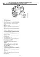
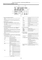
Time code section Chapter 2 Description of Parts - Time code section 1 2 1 terminal (page 69) Input reference signals when setting the generator lock on the camera unit, or when externally locking the time code. @@NOTE tt Supply Y signals of HD or or composite signals as an input signal. However, the sub-carrier of the composite signal on the camera cannot be externally locked. 2 terminal (page 63) ffSwitch input/output in the menu. ffInput the reference time code to this terminal when the time code is locked. ffConnect to the time code input terminal of the external device when locking the time code of the external device to the time code on the camera. (page 70) 3 button The time data indication on the counter display area is retained for the duration that this button is held down. However, the time code generator continues to advance. Press again reactivates the counter. This function is used to learn the time code or counter value of a particular recorded scene. When the screen other than the [HOME] screen of SmartUI is displayed, the function corresponding to each setting screen is executed. 4 (counter display selector) button (page 29) Each press of this button displays the counter value, time code, user bits, and frame rate information on the viewfinder screen. When the screen other than the [HOME] screen of SmartUI is displayed, the function corresponding to each setting screen is executed. 5 button Reset the counter value in the time code display area to 0 (zero). When the screen other than the [HOME] screen of SmartUI is displayed, the function corresponding to each setting screen is executed. - 27 - 345 HOLD COUNTER RESET MONITOR SEL LIGHT TC NDF SLABE P -REC CAM MEDIA CH1 A E F BATT CH2 E F 0 -10 -18 -20 AUDIO -30 SETUP dB 12 HOME /REW STOP KEY LOCK FF/ PLAY/PAUSE THUMBNAIL SET TOP SHIFT EXIT MULTI SEL MENU CANCEL BOTTOM
-
 1
1 -
2
-
3
-
4
-
5
-
6
-
7
-
8
-
9
-
10
-
11
-
12
-
13
-
14
-
15
-
16
-
17
-
18
-
19
-
20
-
21
-
 22
22 -
 23
23 -
 24
24 -
 25
25 -
 26
26 -
 27
27 -
 28
28 -
 29
29 -
 30
30 -
 31
31 -
 32
32 -
33
-
34
-
35
-
36
-
37
-
38
-
39
-
40
-
41
-
42
-
43
-
44
-
45
-
46
-
47
-
48
-
49
-
50
-
51
-
52
-
53
-
54
-
55
-
56
-
57
-
58
-
59
-
60
-
61
-
62
-
63
-
64
-
65
-
66
-
67
-
68
-
69
-
70
-
71
-
72
-
73
-
74
-
75
-
76
-
77
-
78
-
79
-
80
-
81
-
82
-
83
-
84
-
85
-
86
-
87
-
88
-
89
-
90
-
91
-
92
-
93
-
94
-
95
-
96
-
97
-
98
-
99
-
100
-
101
-
102
-
103
-
104
-
105
-
106
-
107
-
108
-
109
-
110
-
111
-
112
-
113
-
114
-
115
-
116
-
117
-
118
-
119
-
120
-
121
-
122
-
123
-
124
-
125
-
126
-
127
-
128
-
129
-
130
-
131
-
132
-
133
-
134
-
135
-
136
-
137
-
138
-
139
-
140
-
141
-
142
-
143
-
144
-
145
-
146
-
147
-
148
-
149
-
150
-
151
-
152
-
153
-
154
-
155
-
156
-
157
-
158
-
159
-
160
-
161
-
162
-
163
-
164
-
165
-
166
-
167
-
168
-
169
-
170
-
171
-
172
-
173
-
174
-
175
-
176
-
177
-
178
 |
 |
