Brother International Entrepreneur PR-650 Users Manual - English - Page 234
Attaching the cap frame
 |
View all Brother International Entrepreneur PR-650 manuals
Add to My Manuals
Save this manual to your list of manuals |
Page 234 highlights
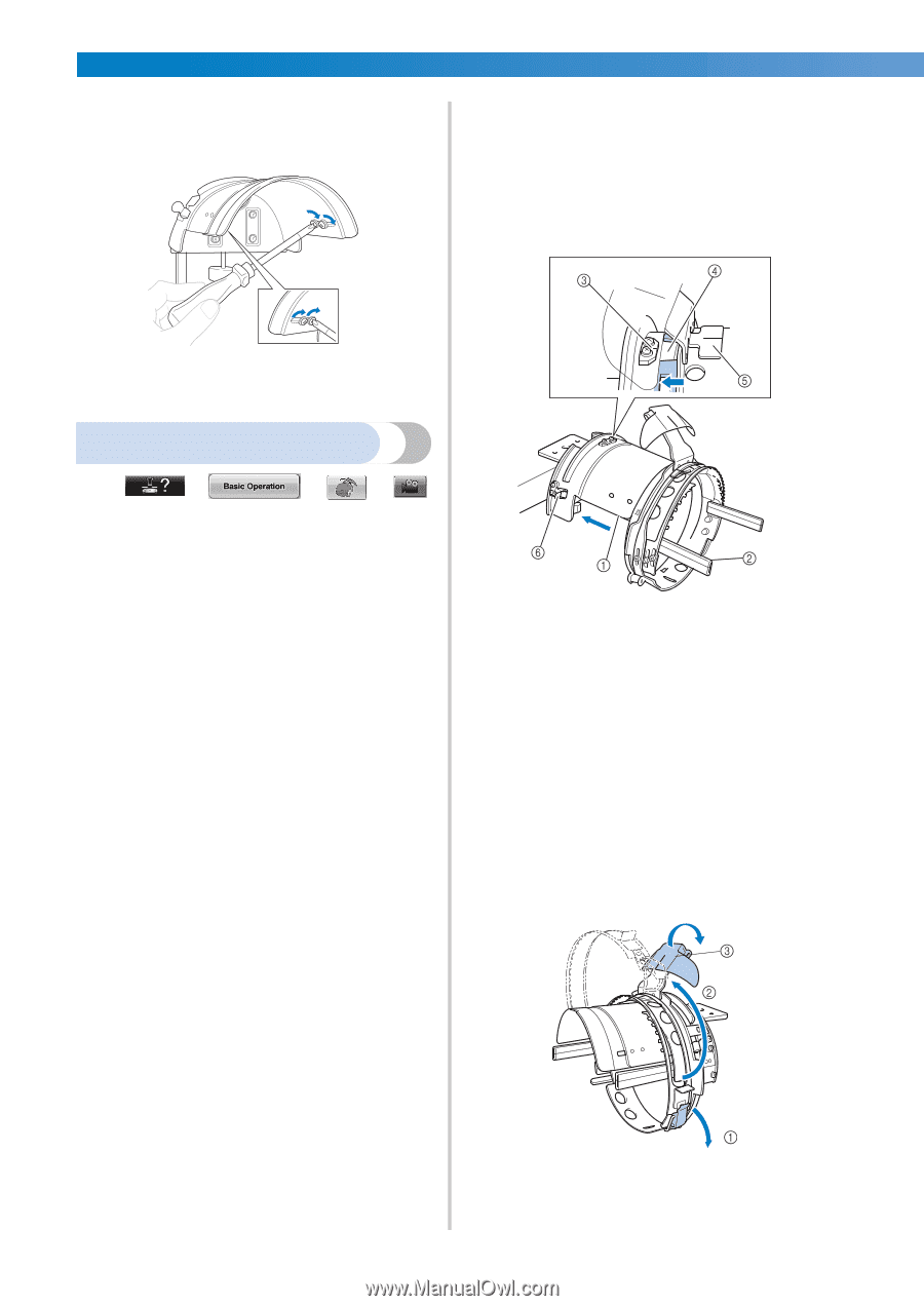
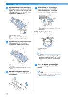
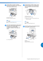
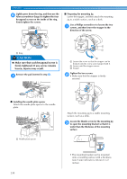
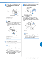
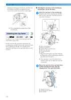
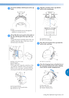
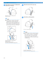
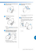
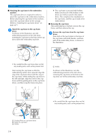
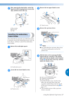
APPENDIX Pull the mounting jig toward you, and then use the Phillips screwdriver to tighten the four screws (two on the left and two on the right). ■ Attaching the cap frame to the mounting jig and putting a cap into the frame Attach the cap frame to the mounting jig. 1 Align the side of the mounting jig with the brace on the cap frame, and then push the cap frame into place. X This completes the preparation of the mounting jig. Attaching the cap frame Touch → → → in order to view a video of the operation on the LCD (refer to page 206). Put the cap into the cap frame attached to the mounting jig, and then remove the cap frame from the mounting jig with the cap clamped. Next, attach the cap frame to the cap frame driver on the machine. 1 Side of mounting jig 2 Brace on cap frame 3 Guiding Plate on mounting jig 4 Notch on cap frame 5 Sweat guard holder 6 Holder • Align the notch in the cap frame with the guiding plate on the mounting jig, and then snap the frame into place. X The cap frame is secured with the two holders (clips) one on right side and one on left side. Release the snap lock on the cap frame down 2 and then disengage the latch. Open the clamping frame. Also, open brim holder. 232 1 Snap lock released 2 Clamping frame opened 3 Brim holder
-
 1
1 -
2
-
3
-
4
-
5
-
6
-
7
-
8
-
9
-
10
-
11
-
12
-
13
-
14
-
15
-
16
-
17
-
18
-
19
-
20
-
21
-
22
-
23
-
24
-
25
-
26
-
27
-
28
-
29
-
30
-
31
-
32
-
33
-
34
-
35
-
36
-
37
-
38
-
39
-
40
-
41
-
42
-
43
-
44
-
45
-
46
-
47
-
48
-
49
-
50
-
51
-
52
-
53
-
54
-
55
-
56
-
57
-
58
-
59
-
60
-
61
-
62
-
63
-
64
-
65
-
66
-
67
-
68
-
69
-
70
-
71
-
72
-
73
-
74
-
75
-
76
-
77
-
78
-
79
-
80
-
81
-
82
-
83
-
84
-
85
-
86
-
87
-
88
-
89
-
90
-
91
-
92
-
93
-
94
-
95
-
96
-
97
-
98
-
99
-
100
-
101
-
102
-
103
-
104
-
105
-
106
-
107
-
108
-
109
-
110
-
111
-
112
-
113
-
114
-
115
-
116
-
117
-
118
-
119
-
120
-
121
-
122
-
123
-
124
-
125
-
126
-
127
-
128
-
129
-
130
-
131
-
132
-
133
-
134
-
135
-
136
-
137
-
138
-
139
-
140
-
141
-
142
-
143
-
144
-
145
-
146
-
147
-
148
-
149
-
150
-
151
-
152
-
153
-
154
-
155
-
156
-
157
-
158
-
159
-
160
-
161
-
162
-
163
-
164
-
165
-
166
-
167
-
168
-
169
-
170
-
171
-
172
-
173
-
174
-
175
-
176
-
177
-
178
-
179
-
180
-
181
-
182
-
183
-
184
-
185
-
186
-
187
-
188
-
189
-
190
-
191
-
192
-
193
-
194
-
195
-
196
-
197
-
198
-
199
-
200
-
201
-
202
-
203
-
204
-
205
-
206
-
207
-
208
-
209
-
210
-
211
-
212
-
213
-
214
-
215
-
216
-
217
-
218
-
219
-
220
-
221
-
222
-
223
-
224
-
225
-
226
-
227
-
228
-
 229
229 -
 230
230 -
 231
231 -
 232
232 -
 233
233 -
 234
234 -
 235
235 -
 236
236 -
 237
237 -
 238
238 -
 239
239 -
240
-
241
-
242
-
243
-
244
-
245
-
246
-
247
-
248
-
249
-
250
-
251
-
252
-
253
-
254
-
255
-
256
-
257
-
258
-
259
-
260
-
261
-
262
-
263
-
264
-
265
-
266
-
267
-
268
-
269
-
270
-
271
-
272
-
273
-
274
-
275
-
276
-
277
-
278
-
279
-
280
 |
 |