IBM 887022X Maintenance Manual - Page 191
connectors
 |
UPC - 000435151957
View all IBM 887022X manuals
Add to My Manuals
Save this manual to your list of manuals |
Page 191 highlights
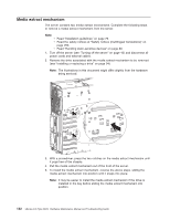
10. Detach the bundled power cable from the chassis: a. Pull the bundled power cable through the slot in the crossbar. b. Slide the two power connectors through the opening on the side of the server ( 3 ). 11. Remove the AC box assembly from the server. 12. To install the AC box assembly, reverse the above steps. Note: When replacing the side panel: a. Line up the tabs on the panel with the notches on the server, then slide back. b. Position the bundled cable towards the bottom of the panel before securing the panel. c. The screw nearest the rear of the server secures both the panel and the AC box assembly mechanism. Chapter 6. FRU information (service only) 181
-
 1
1 -
2
-
3
-
4
-
5
-
6
-
7
-
8
-
9
-
10
-
11
-
12
-
13
-
14
-
15
-
16
-
17
-
18
-
19
-
20
-
21
-
22
-
23
-
24
-
25
-
26
-
27
-
28
-
29
-
30
-
31
-
32
-
33
-
34
-
35
-
36
-
37
-
38
-
39
-
40
-
41
-
42
-
43
-
44
-
45
-
46
-
47
-
48
-
49
-
50
-
51
-
52
-
53
-
54
-
55
-
56
-
57
-
58
-
59
-
60
-
61
-
62
-
63
-
64
-
65
-
66
-
67
-
68
-
69
-
70
-
71
-
72
-
73
-
74
-
75
-
76
-
77
-
78
-
79
-
80
-
81
-
82
-
83
-
84
-
85
-
86
-
87
-
88
-
89
-
90
-
91
-
92
-
93
-
94
-
95
-
96
-
97
-
98
-
99
-
100
-
101
-
102
-
103
-
104
-
105
-
106
-
107
-
108
-
109
-
110
-
111
-
112
-
113
-
114
-
115
-
116
-
117
-
118
-
119
-
120
-
121
-
122
-
123
-
124
-
125
-
126
-
127
-
128
-
129
-
130
-
131
-
132
-
133
-
134
-
135
-
136
-
137
-
138
-
139
-
140
-
141
-
142
-
143
-
144
-
145
-
146
-
147
-
148
-
149
-
150
-
151
-
152
-
153
-
154
-
155
-
156
-
157
-
158
-
159
-
160
-
161
-
162
-
163
-
164
-
165
-
166
-
167
-
168
-
169
-
170
-
171
-
172
-
173
-
174
-
175
-
176
-
177
-
178
-
179
-
180
-
181
-
182
-
183
-
184
-
185
-
 186
186 -
 187
187 -
 188
188 -
 189
189 -
 190
190 -
 191
191 -
 192
192 -
 193
193 -
 194
194 -
 195
195 -
 196
196 -
197
-
198
-
199
-
200
-
201
-
202
-
203
-
204
-
205
-
206
-
207
-
208
-
209
-
210
-
211
-
212
-
213
-
214
-
215
-
216
-
217
-
218
-
219
-
220
-
221
-
222
-
223
-
224
-
225
-
226
-
227
-
228
-
229
-
230
-
231
-
232
-
233
-
234
-
235
-
236
-
237
-
238
-
239
-
240
-
241
-
242
-
243
-
244
-
245
-
246
-
247
-
248
-
249
-
250
-
251
-
252
-
253
-
254
-
255
-
256
-
257
-
258
-
259
-
260
-
261
-
262
-
263
-
264
-
265
-
266
-
267
-
268
-
269
-
270
-
271
-
272
-
273
-
274
-
275
-
276
-
277
-
278
-
279
-
280
-
281
-
282
-
283
-
284
-
285
-
286
-
287
-
288
-
289
-
290
-
291
-
292
-
293
-
294
-
295
-
296
-
297
-
298
-
299
-
300
-
301
-
302
-
303
-
304
-
305
-
306
-
307
-
308
-
309
-
310
-
311
-
312
-
313
-
314
-
315
-
316
-
317
-
318
-
319
-
320
-
321
-
322
-
323
-
324
 |
 |

10.
Detach
the
bundled
power
cable
from
the
chassis:
a.
Pull
the
bundled
power
cable
through
the
slot
in
the
crossbar.
b.
Slide
the
two
power
connectors
through
the
opening
on
the
side
of
the
server
(
±3²
).
11.
Remove
the
AC
box
assembly
from
the
server.
12.
To
install
the
AC
box
assembly,
reverse
the
above
steps.
Note:
When
replacing
the
side
panel:
a.
Line
up
the
tabs
on
the
panel
with
the
notches
on
the
server,
then
slide
back.
b.
Position
the
bundled
cable
towards
the
bottom
of
the
panel
before
securing
the
panel.
c.
The
screw
nearest
the
rear
of
the
server
secures
both
the
panel
and
the
AC
box
assembly
mechanism.
Chapter
6.
FRU
information
(service
only)
181