Oki ML591 MICROLINE Reference Manual - Page 164
Appendix A: Interfacing, Parallel Interface
 |
View all Oki ML591 manuals
Add to My Manuals
Save this manual to your list of manuals |
Page 164 highlights
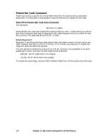
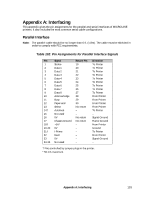
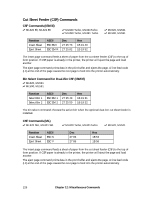
Appendix A: Interfacing This appendix gives the pin assignments for the parallel and serial interfaces of MICROLINE printers. It also includes the most common serial cable configurations. Parallel Interface Note: The parallel cable should be no longer than 6 ft. (1.8m). The cable must be shielded in order to comply with FCC requirements. Table 102: Pin Assignments for Parallel Interface Signals Pin 1 2 3 4 5 6 7 8 9 10 11 12 13 14† 15 16 17 18† 19-30 31† 32 33 34-35 Signal Strobe Data 1 Data 2 Data 3 Data 4 Data 5 Data 6 Data 7 Data 8 Acknowledge Busy Paper end Select Autofeed Not used 0V Chassis Ground +5V* 0V I-Prime Fault 0V Not used Return Pin 19 20 21 22 23 24 25 26 27 28 29 30 No return - - No return No return - - - - - - Direction To Printer To Printer To Printer To Printer To Printer To Printer To Printer To Printer To Printer From Printer From Printer From Printer From Printer To Printer - Signal Ground Frame Ground From Printer Ground To Printer From Printer Signal Ground - † Pins controlled by jumper plugs in the printer. * 50 mA maximum. Appendix A: Interfacing 133
-
 1
1 -
2
-
3
-
4
-
5
-
6
-
7
-
8
-
9
-
10
-
11
-
12
-
13
-
14
-
15
-
16
-
17
-
18
-
19
-
20
-
21
-
22
-
23
-
24
-
25
-
26
-
27
-
28
-
29
-
30
-
31
-
32
-
33
-
34
-
35
-
36
-
37
-
38
-
39
-
40
-
41
-
42
-
43
-
44
-
45
-
46
-
47
-
48
-
49
-
50
-
51
-
52
-
53
-
54
-
55
-
56
-
57
-
58
-
59
-
60
-
61
-
62
-
63
-
64
-
65
-
66
-
67
-
68
-
69
-
70
-
71
-
72
-
73
-
74
-
75
-
76
-
77
-
78
-
79
-
80
-
81
-
82
-
83
-
84
-
85
-
86
-
87
-
88
-
89
-
90
-
91
-
92
-
93
-
94
-
95
-
96
-
97
-
98
-
99
-
100
-
101
-
102
-
103
-
104
-
105
-
106
-
107
-
108
-
109
-
110
-
111
-
112
-
113
-
114
-
115
-
116
-
117
-
118
-
119
-
120
-
121
-
122
-
123
-
124
-
125
-
126
-
127
-
128
-
129
-
130
-
131
-
132
-
133
-
134
-
135
-
136
-
137
-
138
-
139
-
140
-
141
-
142
-
143
-
144
-
145
-
146
-
147
-
148
-
149
-
150
-
151
-
152
-
153
-
154
-
155
-
156
-
157
-
158
-
 159
159 -
 160
160 -
 161
161 -
 162
162 -
 163
163 -
 164
164 -
 165
165 -
 166
166 -
 167
167 -
 168
168 -
 169
169 -
170
-
171
-
172
-
173
-
174
-
175
-
176
-
177
-
178
-
179
-
180
 |
 |