Oki ML591 MICROLINE Reference Manual - Page 94
Parameters L, and H, gives a value of 0 for H
 |
View all Oki ML591 manuals
Add to My Manuals
Save this manual to your list of manuals |
Page 94 highlights
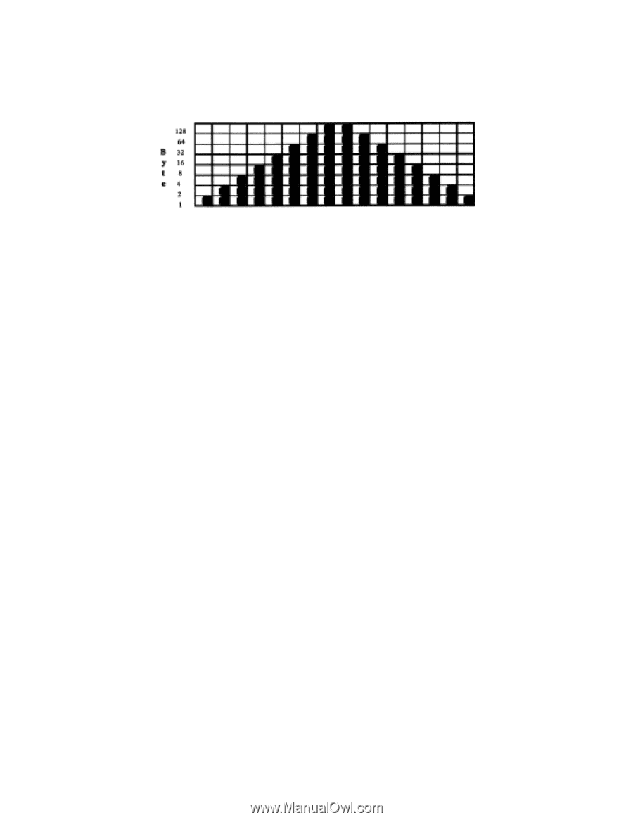
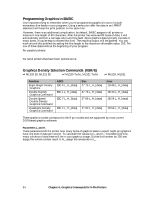
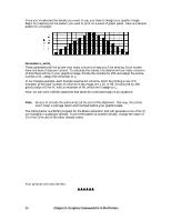
Once you've selected the density you want to use, you have to design your graphic image. Begin by mapping out the pattern you want to print on a piece of graph paper. Here is a sample pattern for a triangle: Parameters Ln and Hn These parameters tell the printer how many columns of data you'll be sending: 8-pin modes have one byte of data per column. To calculate the values, first determine how many columns of dots there will be in your graphics image. Divide this number by 256 and assign the whole number to Hn; assign the remainder to Ln. In our triangle example, each triangle requires 16 columns. We'll be printing a row of 6 triangles, so the total number of columns in the image is 6 x 16, or 96. Dividing 96 by 256 gives a value of 0 for Hn with a remainder of 96, which we'll assign to Ln. Next, we can write a BASIC statement that sends the command begin 8-pin graphics: LPRINT CHR$(27);"*";CHR$(3);CHR$(96);CHR$(0); Note: Be sure to include the semicolon(;) at the end of this statement. That way, the printer won't insert a carriage return and line feed before your graphics data. The listing below is a BASIC program for the Epson emulation that will generate a row of six of our triangles in quadruple density. To print the pattern at another density, change the value of D in line 10 to one of the other density codes. 10 D=3 'Density code for quadruple density (Epson) 20 WIDTH "LPT1:",255 'Set printer for maximum line width 30 LPRINT CHR$(27);"*";CHR$(D);CHR$(96);CHR$(0); 40 REM CHR$(D) is the density; in this case D=3 for quadruple density 50 REM CHR$(96) and CHR$(0) indicate the number of columns 60 FOR I=1 TO 6 'Repeat triangle pattern six times 70 FOR J=1 TO 16 'Each triangle has 16 columns 80 READ A 'Read the column 90 LPRINT CHR$(A); 'Send the byte to the printer 100 NEXT J 'Now print the next column 110 RESTORE 'Go back to the beginning of the DATA statements 120 NEXT I 'Now print the next triangle 130 END 140 DATA 1,3,7,15,31,63,127,255,255,127,63,31,15,7,3,1 Your printout will look like this: 56 Chapter 6: Graphics Commands for 9-Pin Printers
-
 1
1 -
2
-
3
-
4
-
5
-
6
-
7
-
8
-
9
-
10
-
11
-
12
-
13
-
14
-
15
-
16
-
17
-
18
-
19
-
20
-
21
-
22
-
23
-
24
-
25
-
26
-
27
-
28
-
29
-
30
-
31
-
32
-
33
-
34
-
35
-
36
-
37
-
38
-
39
-
40
-
41
-
42
-
43
-
44
-
45
-
46
-
47
-
48
-
49
-
50
-
51
-
52
-
53
-
54
-
55
-
56
-
57
-
58
-
59
-
60
-
61
-
62
-
63
-
64
-
65
-
66
-
67
-
68
-
69
-
70
-
71
-
72
-
73
-
74
-
75
-
76
-
77
-
78
-
79
-
80
-
81
-
82
-
83
-
84
-
85
-
86
-
87
-
88
-
 89
89 -
 90
90 -
 91
91 -
 92
92 -
 93
93 -
 94
94 -
 95
95 -
 96
96 -
 97
97 -
 98
98 -
 99
99 -
100
-
101
-
102
-
103
-
104
-
105
-
106
-
107
-
108
-
109
-
110
-
111
-
112
-
113
-
114
-
115
-
116
-
117
-
118
-
119
-
120
-
121
-
122
-
123
-
124
-
125
-
126
-
127
-
128
-
129
-
130
-
131
-
132
-
133
-
134
-
135
-
136
-
137
-
138
-
139
-
140
-
141
-
142
-
143
-
144
-
145
-
146
-
147
-
148
-
149
-
150
-
151
-
152
-
153
-
154
-
155
-
156
-
157
-
158
-
159
-
160
-
161
-
162
-
163
-
164
-
165
-
166
-
167
-
168
-
169
-
170
-
171
-
172
-
173
-
174
-
175
-
176
-
177
-
178
-
179
-
180
 |
 |