Oki ML591 MICROLINE Reference Manual - Page 91
Graphics Commands for 9-Pin Printers, Overview
 |
View all Oki ML591 manuals
Add to My Manuals
Save this manual to your list of manuals |
Page 91 highlights
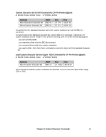
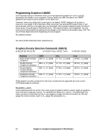
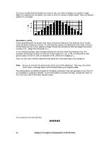
Chapter 6: Graphics Commands for 9-Pin Printers Overview Your printhead has one column of pins. Images are created as the pins "fire," striking the ribbon against the paper to produce dots. White spaces appear where the pins don't fire. In 8pin graphics, each column of dots is represented by a single byte of data. Models ML320, ML321, ML320 Turbo, ML321 Turbo, ML520, and ML521 use the 9-pin mode in cases where a slightly higher resolution is required: it uses two bytes to represent each dot column. When you program a graphic image, your program has to describe the pattern of dots you want to print. Graphics data, like all other data sent to the printer, consists of a series of bytes. Each of the eight bits in a byte of graphics data corresponds to one pin on the printhead. A bit's value can be either 1 or 0. When the printer receives the data, it interprets a bit with a value of 1 as a command to fire the corresponding pin. Bits that are set to 0 don't cause pins to fire. You can picture the byte as a column of 8 bits. In 8-pin graphics, the body of data is a series of these columns lined up next to each other. Instead of sending the data to the printer bit by bit, you'll probably want to convert this binary information into decimal or hexadecimal format for use with your programming language. In the figure below we show how to determine the decimal value for a given pattern of pins. For optimum registration when printing graphics using bi-directional printing, use the Print Registration item in the printer menu to fine-tune the alignment of the vertical bars which print as part of the menu. Keep changing the setting until the lines of the vertical bar characters have the straightest vertical column. Chapter 6: Graphics Commands for 9-Pin Printers 53
-
 1
1 -
2
-
3
-
4
-
5
-
6
-
7
-
8
-
9
-
10
-
11
-
12
-
13
-
14
-
15
-
16
-
17
-
18
-
19
-
20
-
21
-
22
-
23
-
24
-
25
-
26
-
27
-
28
-
29
-
30
-
31
-
32
-
33
-
34
-
35
-
36
-
37
-
38
-
39
-
40
-
41
-
42
-
43
-
44
-
45
-
46
-
47
-
48
-
49
-
50
-
51
-
52
-
53
-
54
-
55
-
56
-
57
-
58
-
59
-
60
-
61
-
62
-
63
-
64
-
65
-
66
-
67
-
68
-
69
-
70
-
71
-
72
-
73
-
74
-
75
-
76
-
77
-
78
-
79
-
80
-
81
-
82
-
83
-
84
-
85
-
 86
86 -
 87
87 -
 88
88 -
 89
89 -
 90
90 -
 91
91 -
 92
92 -
 93
93 -
 94
94 -
 95
95 -
 96
96 -
97
-
98
-
99
-
100
-
101
-
102
-
103
-
104
-
105
-
106
-
107
-
108
-
109
-
110
-
111
-
112
-
113
-
114
-
115
-
116
-
117
-
118
-
119
-
120
-
121
-
122
-
123
-
124
-
125
-
126
-
127
-
128
-
129
-
130
-
131
-
132
-
133
-
134
-
135
-
136
-
137
-
138
-
139
-
140
-
141
-
142
-
143
-
144
-
145
-
146
-
147
-
148
-
149
-
150
-
151
-
152
-
153
-
154
-
155
-
156
-
157
-
158
-
159
-
160
-
161
-
162
-
163
-
164
-
165
-
166
-
167
-
168
-
169
-
170
-
171
-
172
-
173
-
174
-
175
-
176
-
177
-
178
-
179
-
180
 |
 |
